The WIDAR Correlator room fire detection and suppression system is a 'Total Flood' clean agent gaseous
fire suppression system with an addressable detection and control system. In the event the fire is not
extinguished with the gaseous system a 'dry-pipe' water sprinkler system will discharge. Automatic
and manual discharge options are incorporated into the control scheme with abort capabilities at
different stages.
On June 17, 2020 the Shunt Trip Bypass Switch was replaced and tested. While so doing,
other items in the room such as the Emergency Stop switches and the yellow Abort buttons
were also tested and discussed with EMI as to their precise functionality.
The web page was updated to reflect this new informaton. Specifically the folloing areas
were added or updated:
The EVLA Correlator fire detection and suppression system consists of three subsystems:
Fike FM-200 Fire Suppression System. FM-200 was introduced in 1993 as a replacement
for Halon and has gained acceptance as the world's leading clean gaseous fire extinguishing agent.
FM-200 extinguishes fire via a combination of chemical based fire inhibition and cooling. It is
environmentally acceptable, safe to use with sensitive equipment, fast acting, efficient and
effective. Several smoke detectors in both the ceiling and the floor are a part of the FM-200
system. Two tanks contain the FM-200 gas; one large located outside of the correlator room
that dumps into the room and one smaller tank, located in the room, that dumps into the floor
space.
Fenwal AnaLASER II High Sensitivity Smoke Detector consists of a laser particle
counter detector head and a high efficiency fan module connected to a piping network that spreads
throughout the ceiling of the correlator room. It provides early warning smoke detection.
Tyco DV-5 Red-E Cabinet Integrated Deluge Fire Protection Package is a
pre-assembled fire protection valve package that provides water, via a sprinkler system, as a
last resort if fire presists after the FM-200 dump.
In addition, the two CPCC computers are wired into the Fike FM-200 panel to monitor status of the
smoke detectors and, in the event of fire, power down the correlator in a timely manner to minimize
damage from fire suppressents.
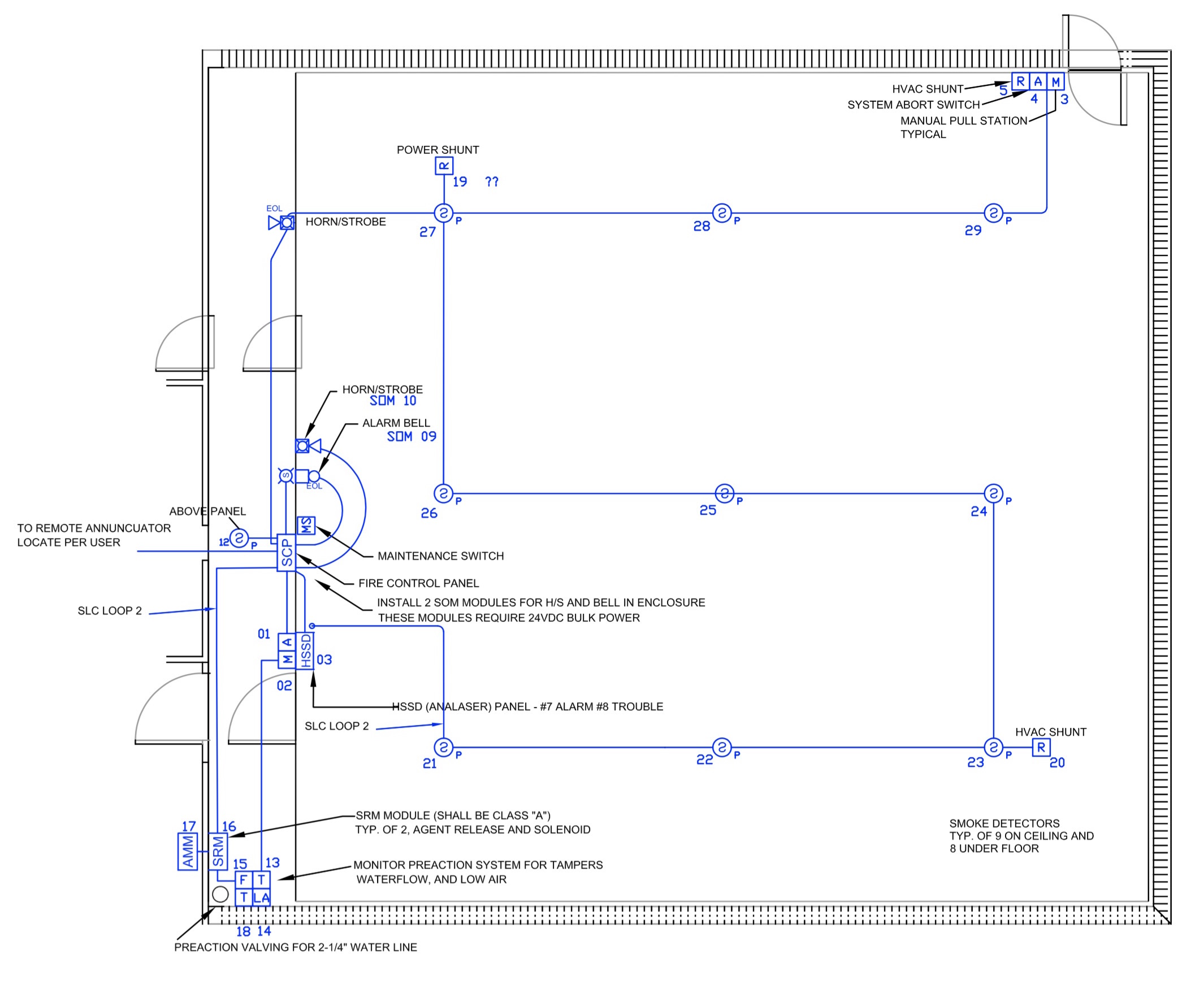
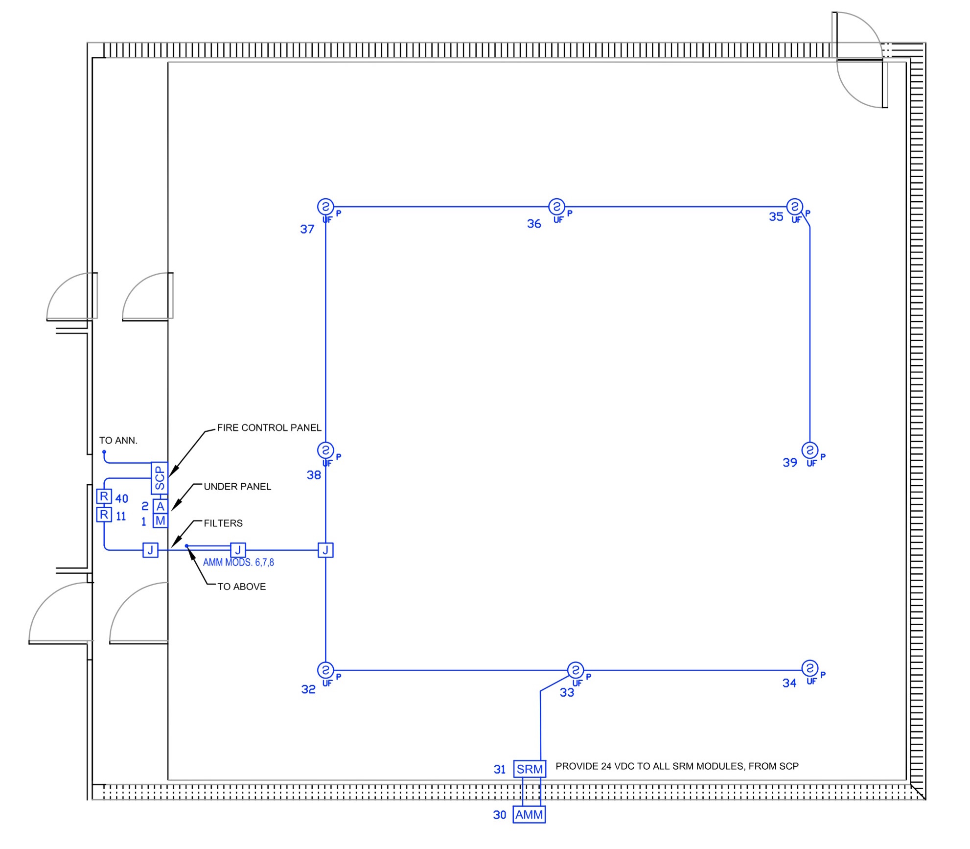
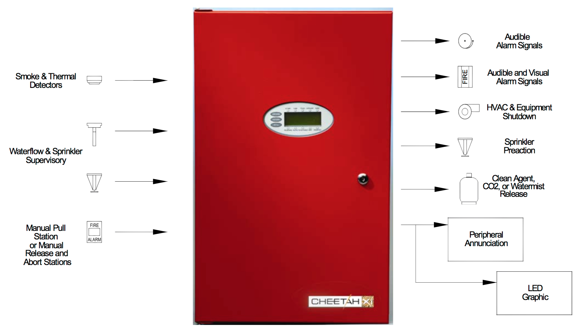
Schematic diagram showing the major compnents of the EVLA Correlator room's fire detection
and suppression system.
Supervisory is caused by the AnaLASER High Sensitivity Smoke Detector. It is
said that this is sensitive enough to be set off by a soldering iron. The Supervisory alarm is
also activated from loss of pressure in the deluge valve system, loss of pressure in the FM-200
tanks, [tbd - find ALL the supervisory alarm triggers]. The operators will see the alarm
on their alarm box and the CPCC's will inticate the alarm on the operator's GUI in the control
room but will take no further action.
First Smoke Detection is when the first Fike smoke detectors activates.
The following actions take place:
'ALARM' lamp illuminates on control panel face,
An alarm bell and visual indicator are energized
Auxillary functions are activated as follows:
Operate door holder/closures on access doors
Shutdown HVAC equipment
Release vent magnetic holders and actuate underfloor fire damper
Send the signal to the CPCC computers (which only indicate the alarm on the Operator's
GUI but take no further action)
Second Smoke Detection is when the second and subsequent Fike smoke detectors
activate. Active automatic fire suppression starts as follows:
Illuminaate 'PRE-DISCHARGE' on control panel face
Energize a pre-discharge horn/strobe device
Send signal to enable preaction (sprinkler) system
Close dampers
Start 60-second shunt trip timer
Send signal to CPCC's which will commence powering off the 320 correlator boards.
This is done in a staged manner to minimize current spikes and takes approximately
50-seconds to complete.
Upon completion of 60-second timer:
Shunt trip is activated removing all power to the room
FM-200 gas is dumped into the room and into the floor space below
"SYSTEM FIRED" lamp is illuminated on control panel face
Outside Discharge Strobe is enabled
Building fire alarm activated
Fuseable links melt closing fire dampers
If the fire is still burning hot enough, it will open a sprinkler head causing a
pressure drop in the sprinkler system piping. The FM-200 is wired into the sprinkler
system to provide an enabling signal when its detectors activate. If both the enabling
signal is present and a pressure drop happens, the sprinklers will activate.
Component Descriptions
Fike FM-200 System
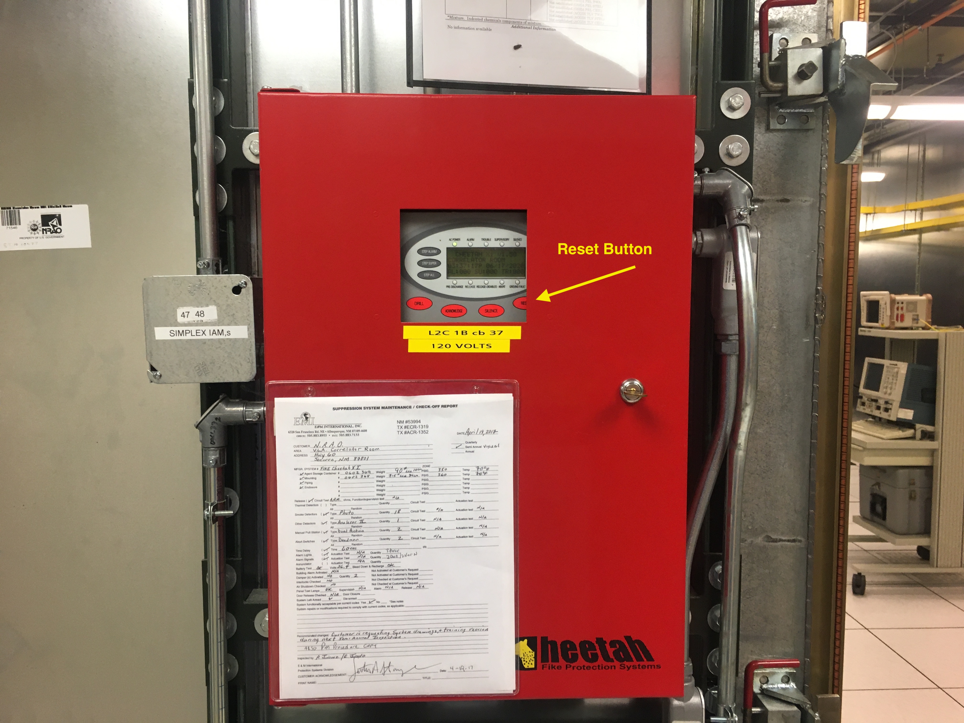
Cheetah Xi Control Panel
The heart of the Fike FM-200 Fire Suppression System is the Cheetah Xi Contol Panel.
All physical devices that are a part of the fire detection and suppression system are connected
to the control panel including the Fenwal AnaLASER, the Tyco sprinklers, the room's HVAC units
and CPCC systems. Some devices, such as the smoke detectors, are input devices and others, such
as HVAC power control and CPCCs are outputs. The major devices that are connected to the control
and that make up the overall system will be discussed individully.
The control panel is discussed in detail in the
Product Manual
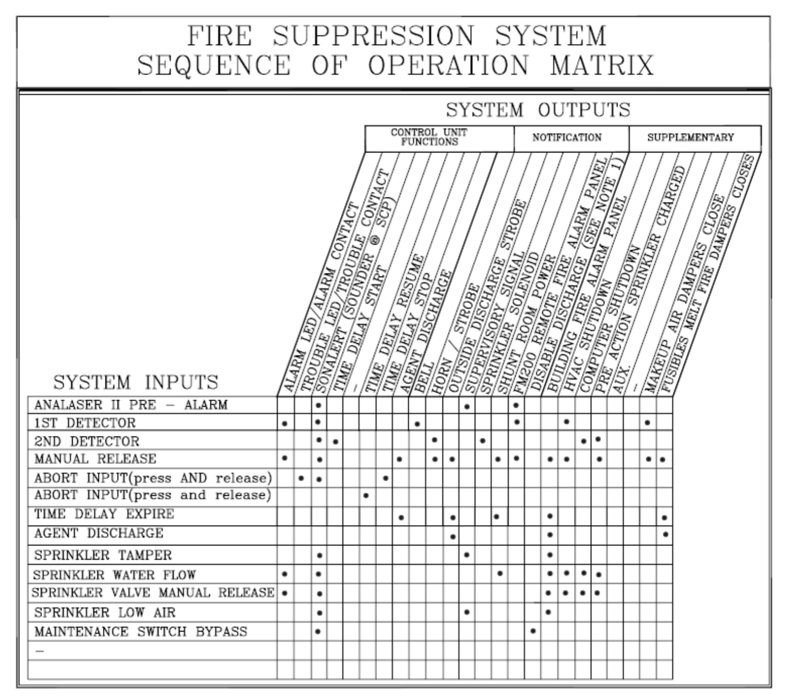
The control panel is the heart of the system. It accepts input 'events' and determines
which output 'actions' will take place accordinagly.
The following matrix correlates to the inputs and outputs of the control panel:
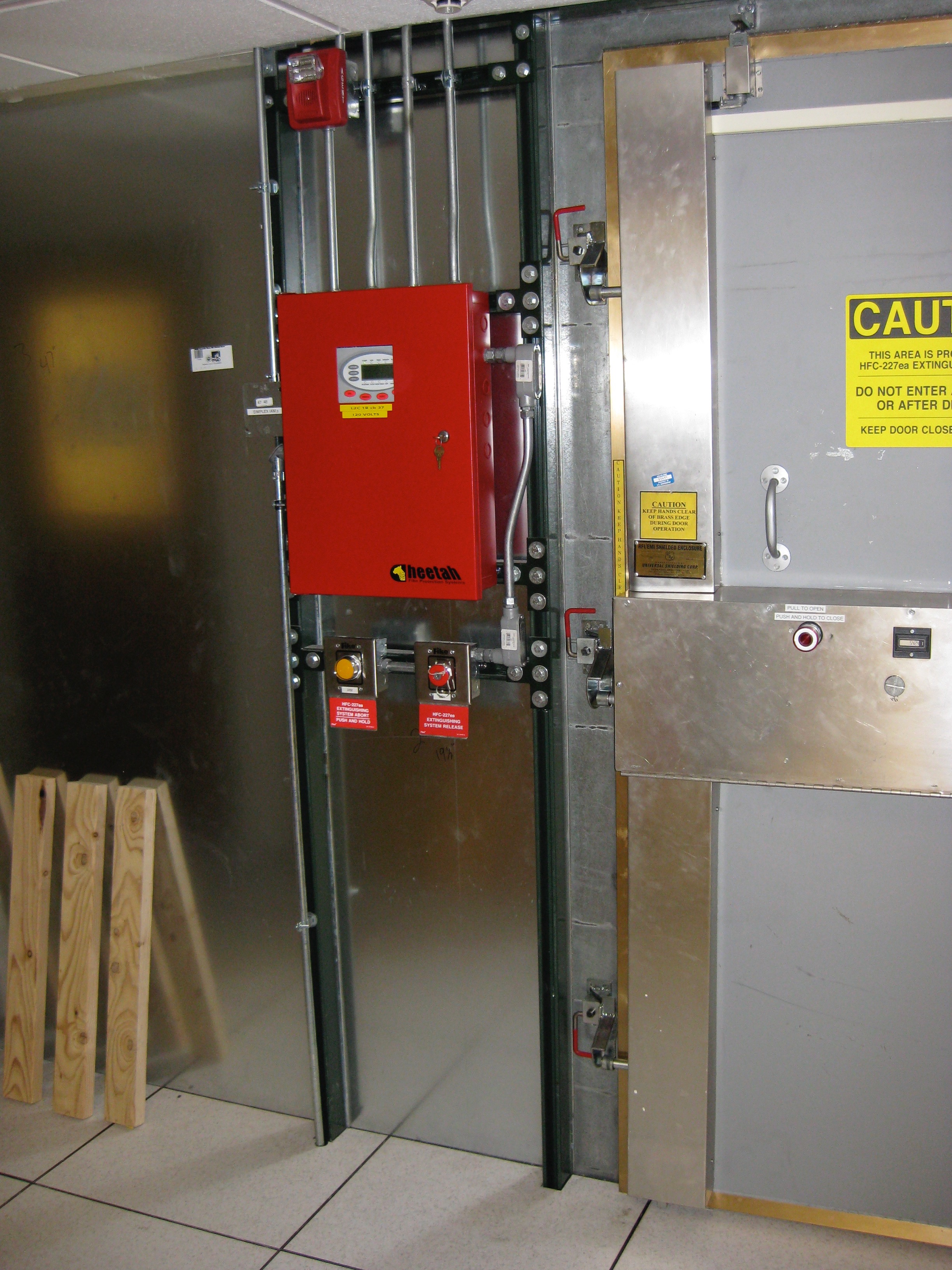
The control panel for the EVLA Correlator is located outside of the correlator room near the
right-side (facing the correlator room from the Operator's area).
The components of the system, such as the emergency manual discharge switches, sprinkler
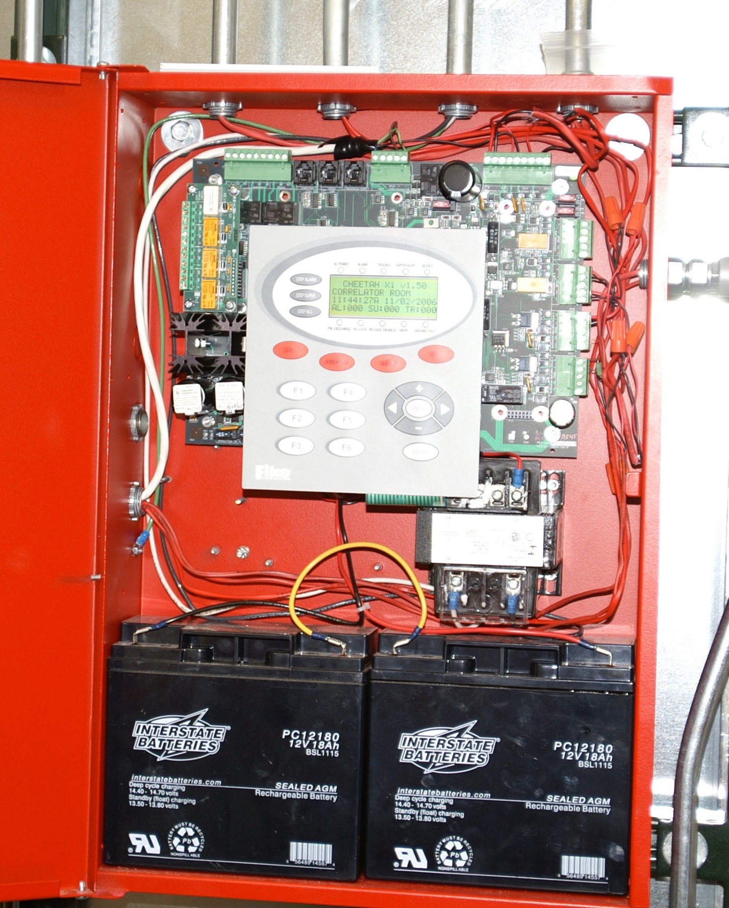
system, FM-200 gas tanks and smoke detectors are all wired into the control panel. The control
panel and the rest of the system is backed up by a 24-volt battery so it will operate independently
of AC power.
In this early photograph the CPCC system has not yet been wired into the contol panel; it will
be shown below in the CPCC section.
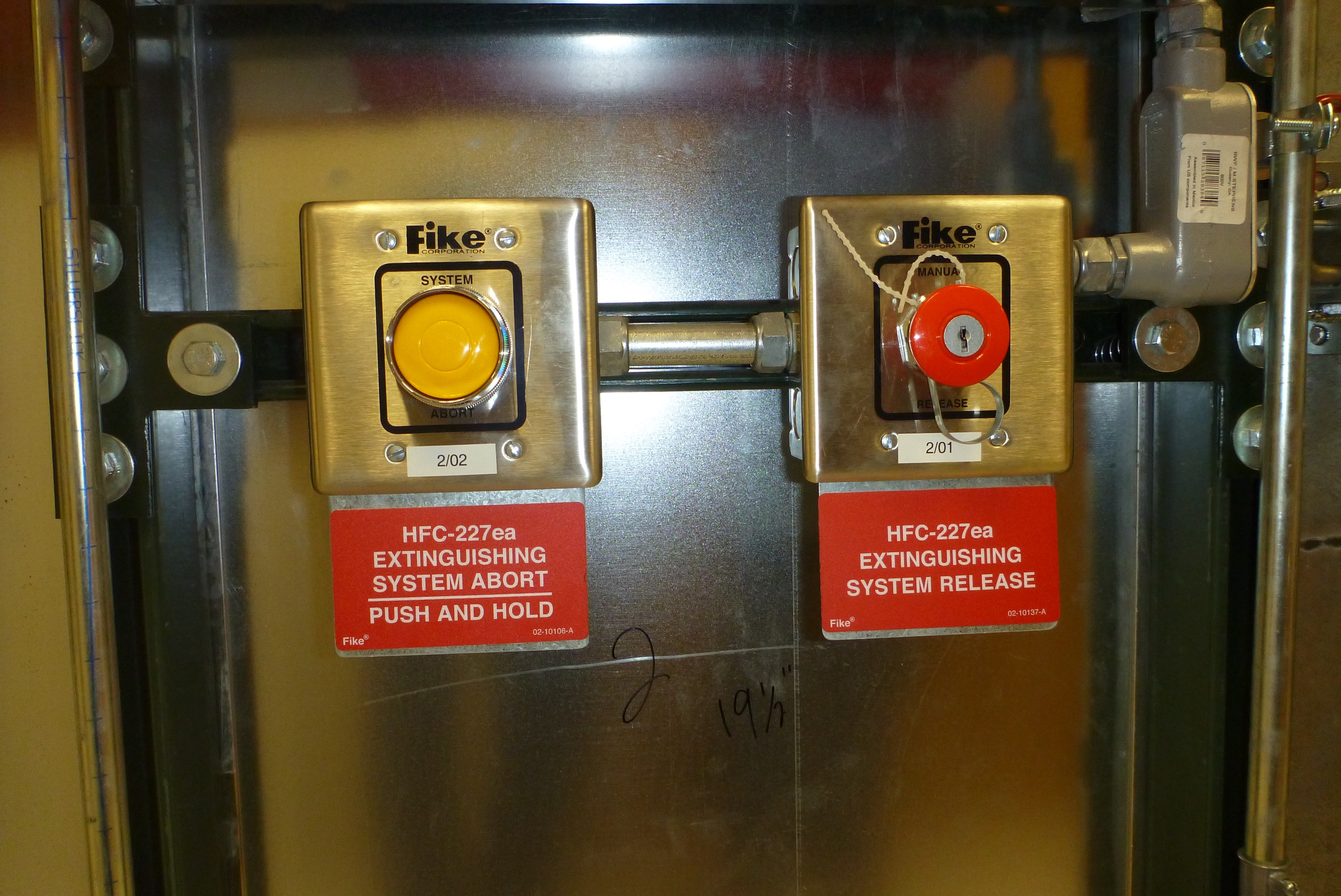
Extinguishing System Release and Abort Buttons
Manual Release and Abort switches used to manually dump the FM-200 suppressent or to abort
the 60-second countdown timer started when a second smoke detector activates.
There are two sets of Manual Release and Abort switches:
Near the emergency exit door at the rear of the room on Northeast wall,
On the outside of the room under the main control panel near the main entrance
on the Northwest wall.
The Red Manual Release Button causes an immediate FM200 Discharge and Shunt Trip
activation. This button should only be activated if fire or smoke is present while an
employee is also present and feels it should be used. Otherwise, the smoke detectors will discharge
the FM200 once two detectors are activated and the 60-second time delay expires. In other words,
the manual dump should only be activated under extreme circumstances; the system was designed to
automatically release the fire suppressant at the appropriate time.
The Yellow Abort Button resets the 60-second timer back to 60 seconds and holds it from
further countdown while the button is held pressed. When released the 60-second count resumes.
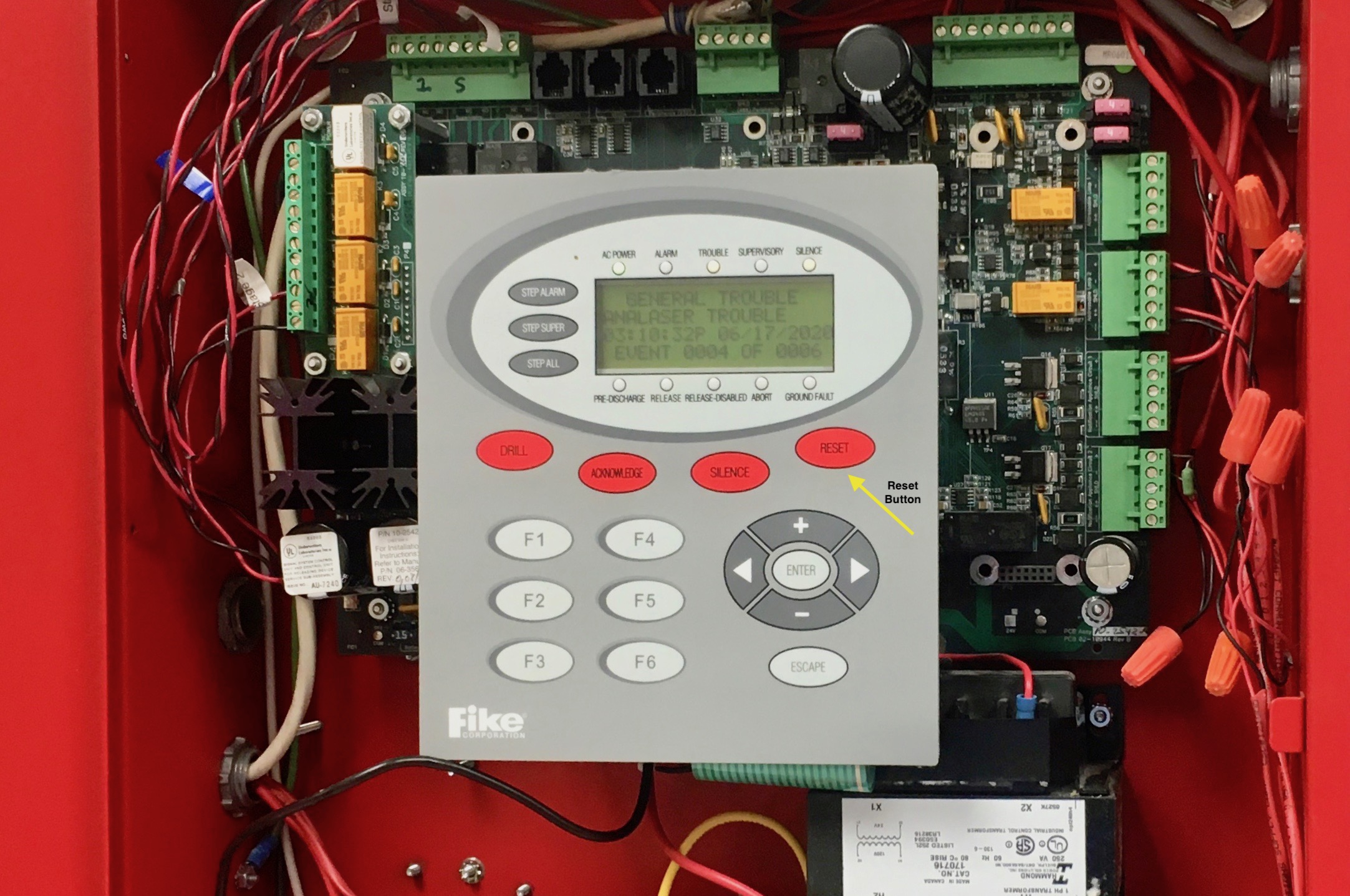
The countdown can be permanently aborted by pressing the 'Reset' button on the Fike Control Panel:
The Reset Button on the Fike Control Panel will stop the 60-second timer for good.
The Reset Button can be accessed even if the panel door is closed and locked.
If two people are in the room and wish to abort the extingquishing agent release and electrical
shunt trip, one can hold a yellow 'Abort' button while the other goes to the Fike Control Panel
to press the 'Reset' button. If only one person is present, they can press and release the
yellow Abort button to give them a full 60-seconds to run to the Fike Control Panel and press
the 'Reset' button.
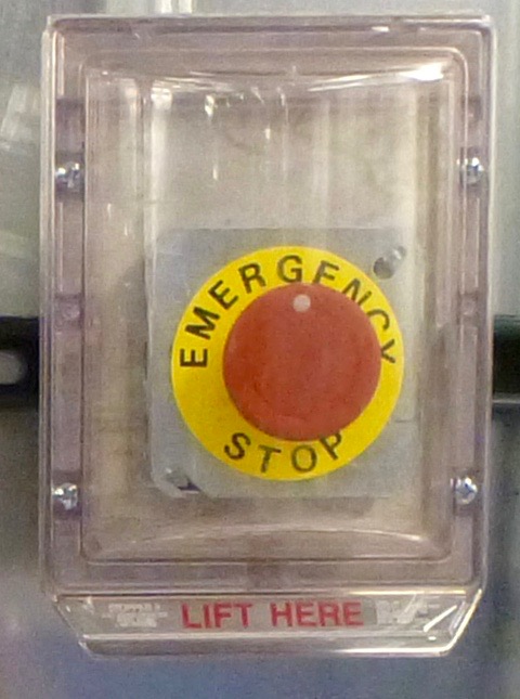
Emergency Stop Buttons
Near each of the three exits is an 'Emergency Stop' Switch.
The three Emergency Stop Buttons are located on the inside of the correlator room near
each of the three doors. These switches will immediately activate the Shunt Trip
Mechanism in the main AC power mains breaker box. This will cut all power to the room.
48V power from the power plant will be disconnected thus shutting down all the correlator racks and
boards. A/C power to the room will be removed turning off the remaining equipment in the room
like the servers, CBE, HVAC units, overhead lights, etc. The room will go dark except for a
battery operated emegency light on the front entrance wall.
The Emergency Stop Switches, when activated, will not cause suppressent release or vent closure.
The Fire Suppression system will remain functional.
The following is a short 9-second video showing the Shunt Trip in action (note: the video is
ineffective without audio - please contact kryan if audio
does not work in your browser):
If the correlator is operating at normal load this sudden loss at such high current levels is
not good for the equipment. Because of this, the shunt trip should not purposely be activated
without the correlator being powered down before hand.
Also for testing purposes the Shunt Trip Mechanism can be bypassed as described next.
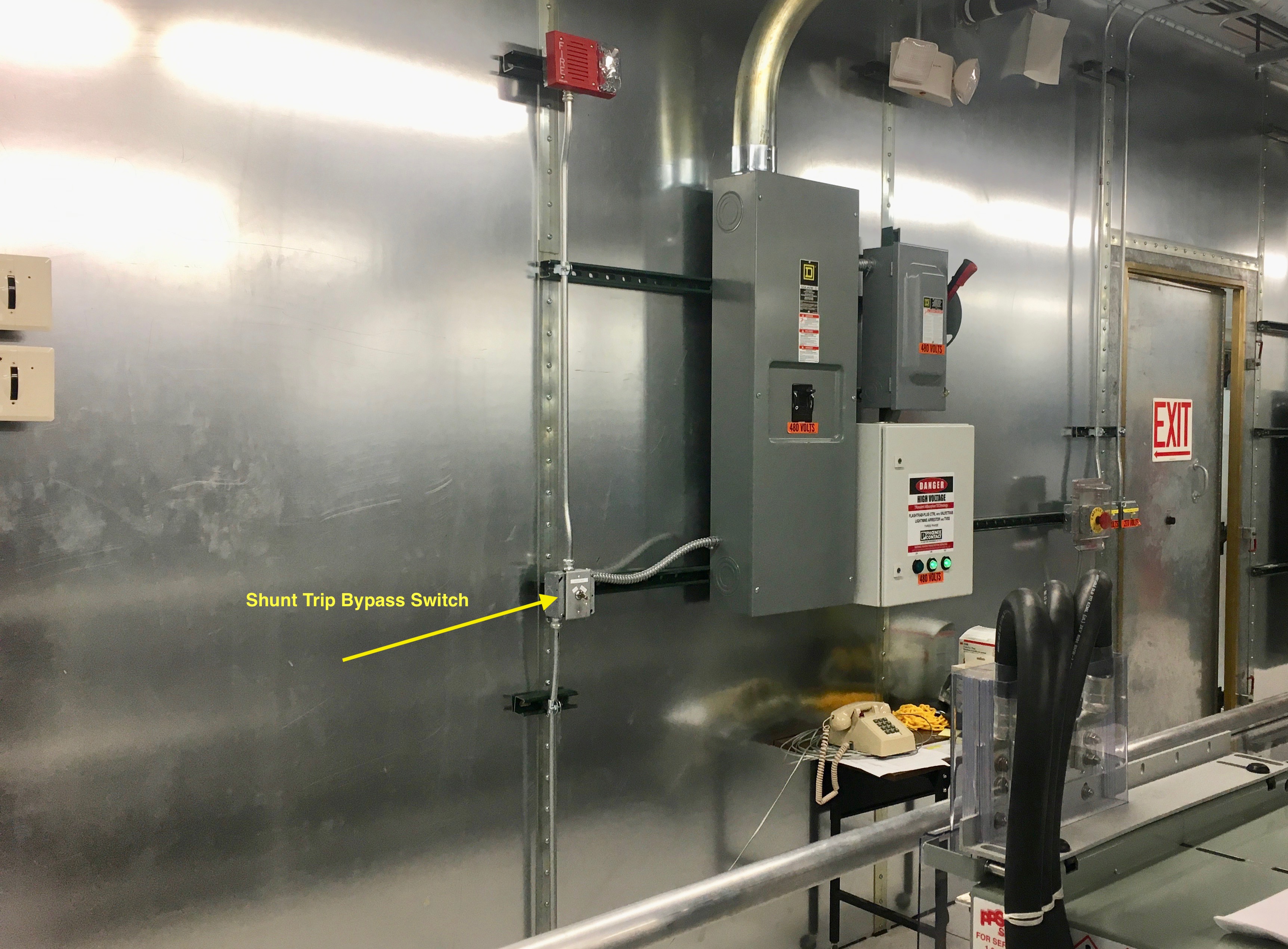
Shunt Trip Bypass Switch
The Shunt Trip Bypass Switch is located inside the correlator room, on the main entrance wall,
between the two doors.
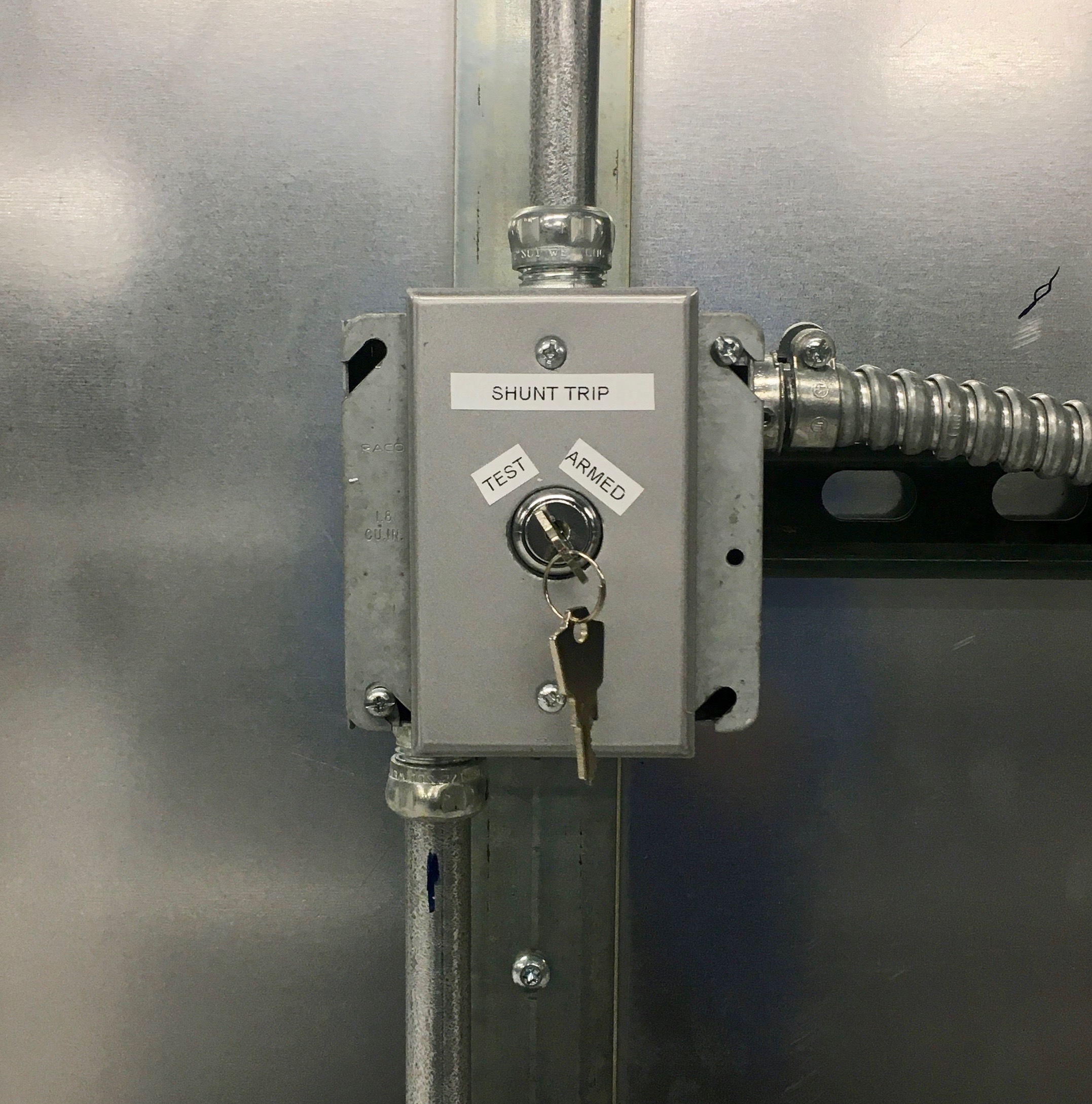
The switch has two positions: 'Test' and 'Armed'.
The Shunt Trip Mechanism can be bypassed for testing purposes. When in the 'Test' position
the shunt trip will not be activated by any means. Also, when the shunt trip is bypassed
('Test' position), it will NOT prevent suppressent release in the event of fire or manual
release button activation.
A new bypass switch was installed June 17, 2020 and tested in both positions with each of the
three Emergency Stop Switches and with the 2nd smoke detector activation 60-second timer
expiration.
FM-200 Fire Suppressent
The EVLA Correlator's Fike fire suppression system uses HFC-227ea, called Heptafluoropropane,
as the first line of fire suppression. HFC-227ea, named 'FM-200' by Dupont falls in the category
of 'Clean Agents' by the NFPA-2001 - Standard for Clean Agent Fire Extinguishing Systems and is
an acceptable replacement for Halon. The term 'Clean Agent' is defined by NFPA-2001 as:
Electrically nonconductive, volatile, or gaseous fire extinguishant that does not leave a residue
upon evaporation.
From www.fireengineering.com:
[FM-200] is a colorless, liquefied gas that is rapidly fully discharged (within 10 seconds)
through nozzles into an area as a clear, nonconductive vapor in fixed total flooding
applications. Relatively low concentrations of this agent (between 4 and 9 percent) are
required in total flooding systems. FM-200® extinguishes fire by removing heat and inhibiting
the chemical chain reaction (fire tetrahedron) inside the flame zone. It is a clean agent that
has acceptable toxicity for use in occupied spaces and is effective on Class A, Class B, and
Class C fires.
FM-200 is safe for humans; in fact, it is also used as the propellent in some asthma inhalers.
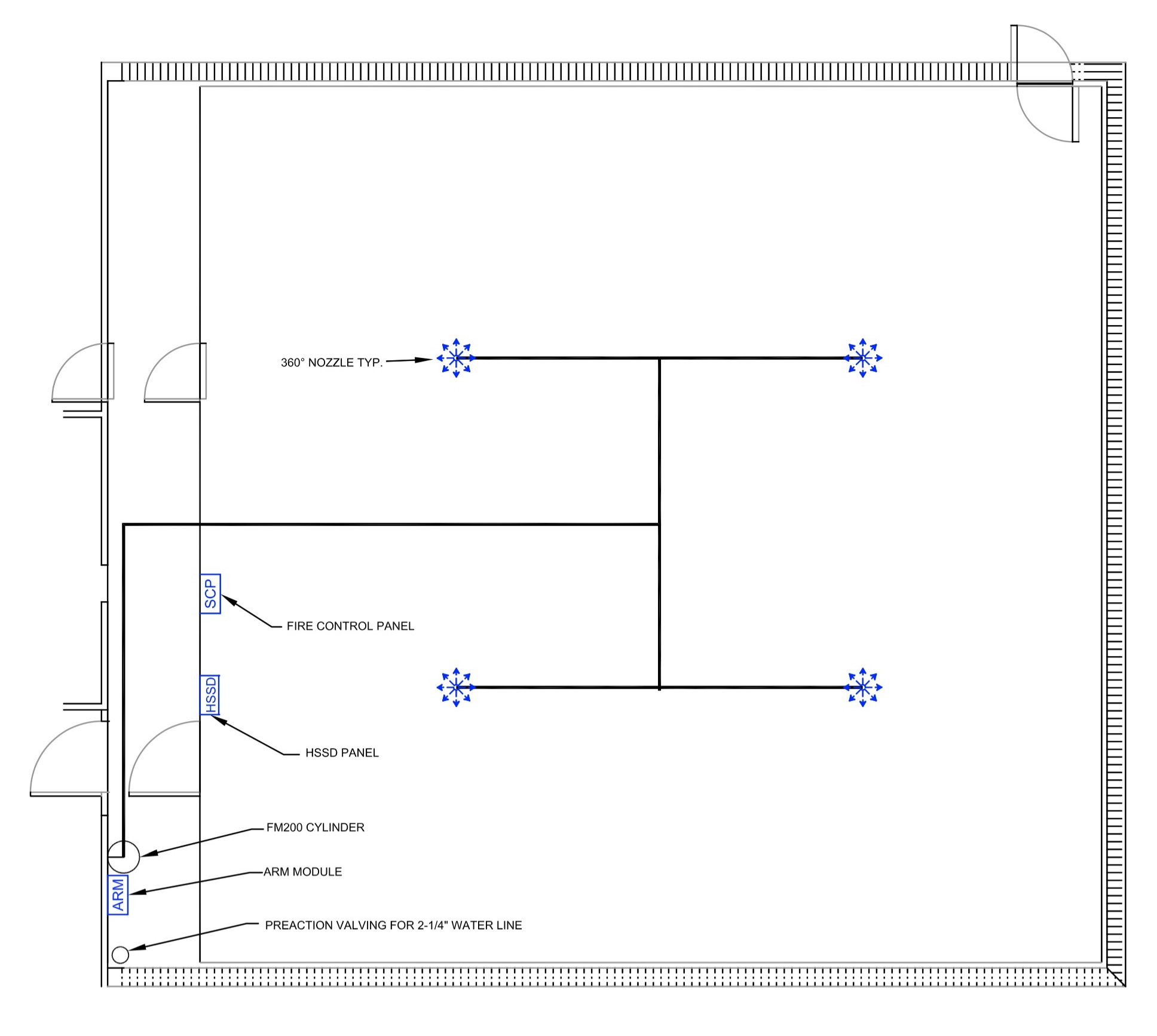
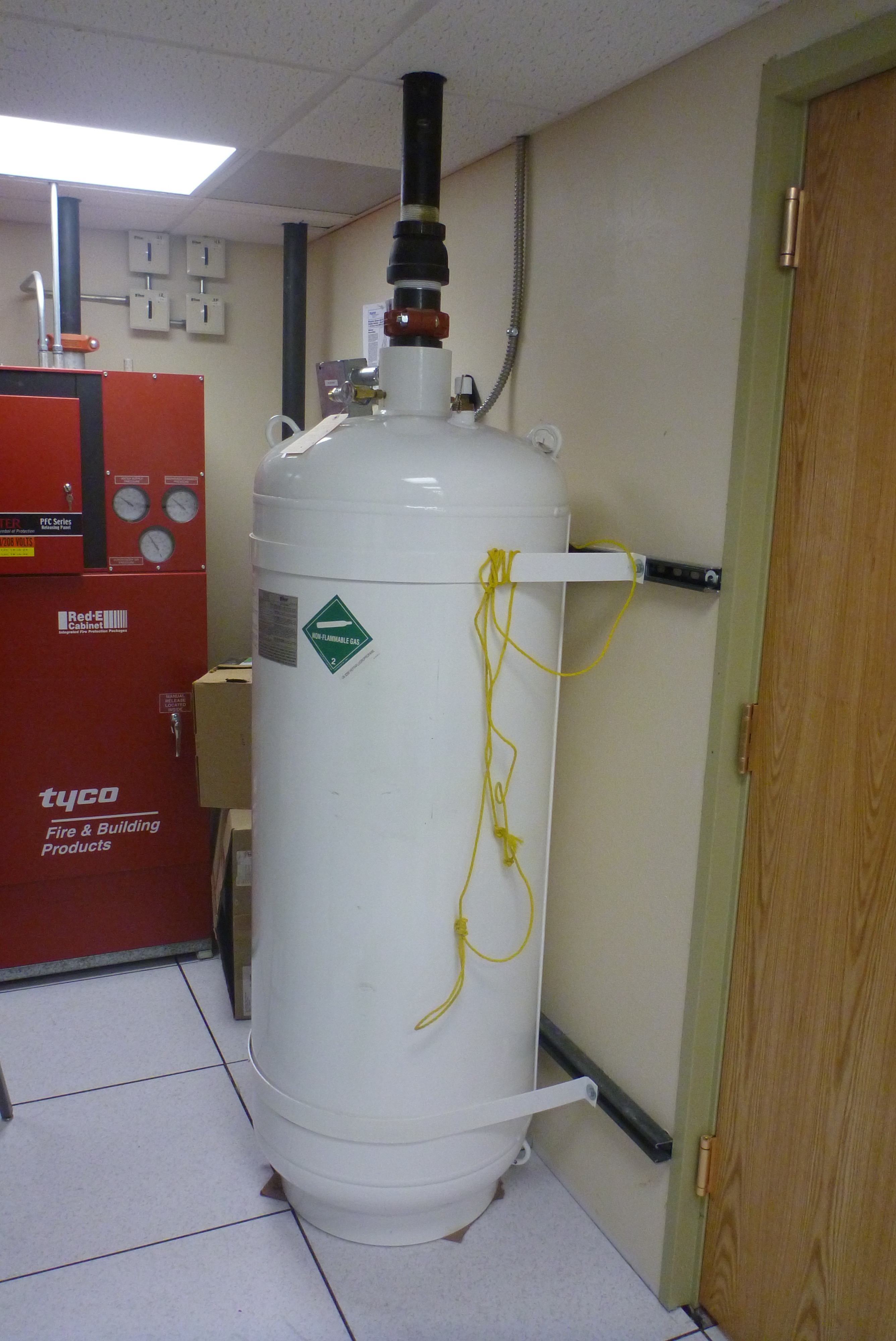
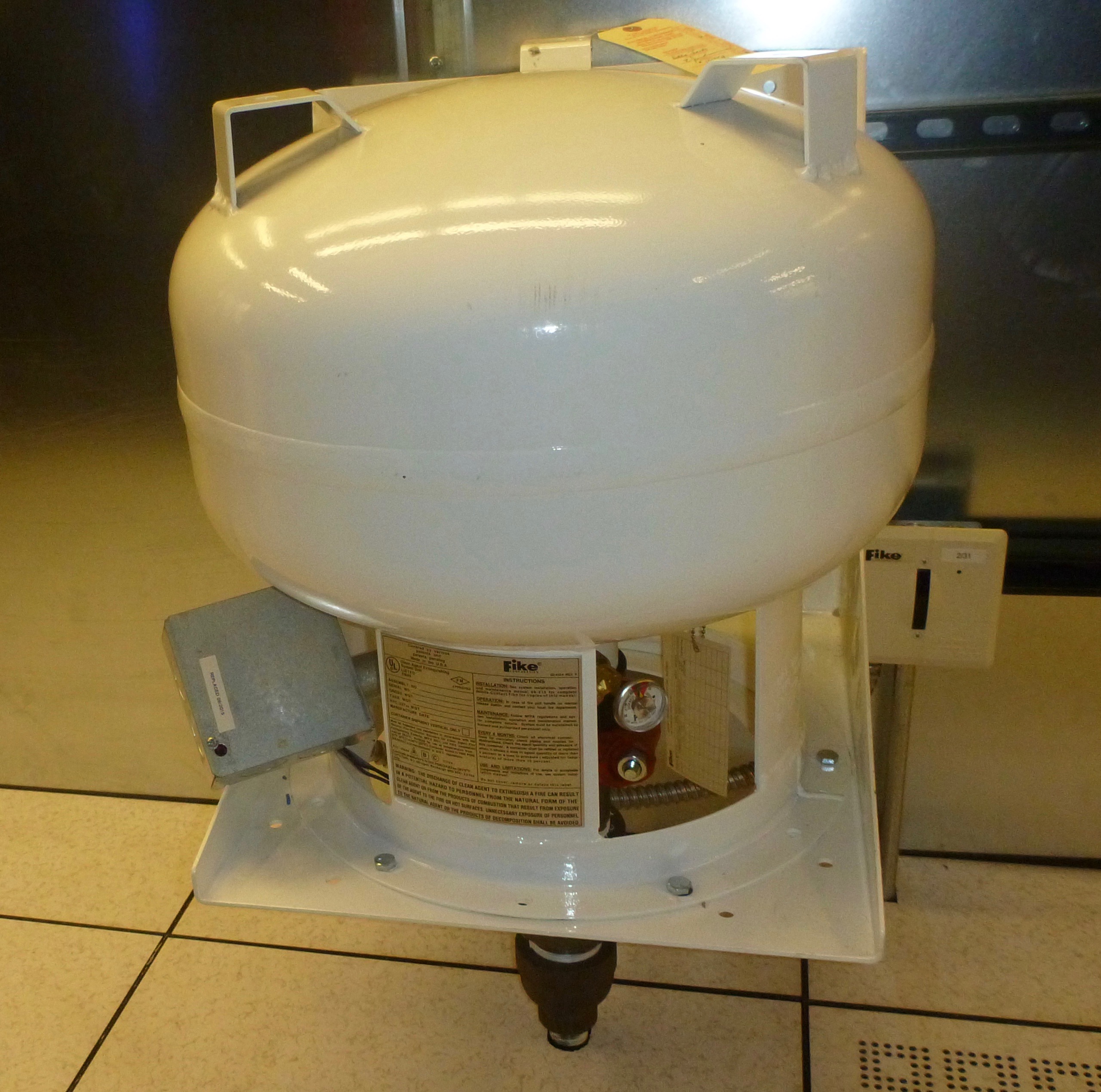
The main FM-200 cylinder is located outside of the correlator room near the Southwest door.
A smaller cyclinder is located inside the correlator room behind the auxillary racks
near the Southwest wall and dumps to the space under the raised floor.
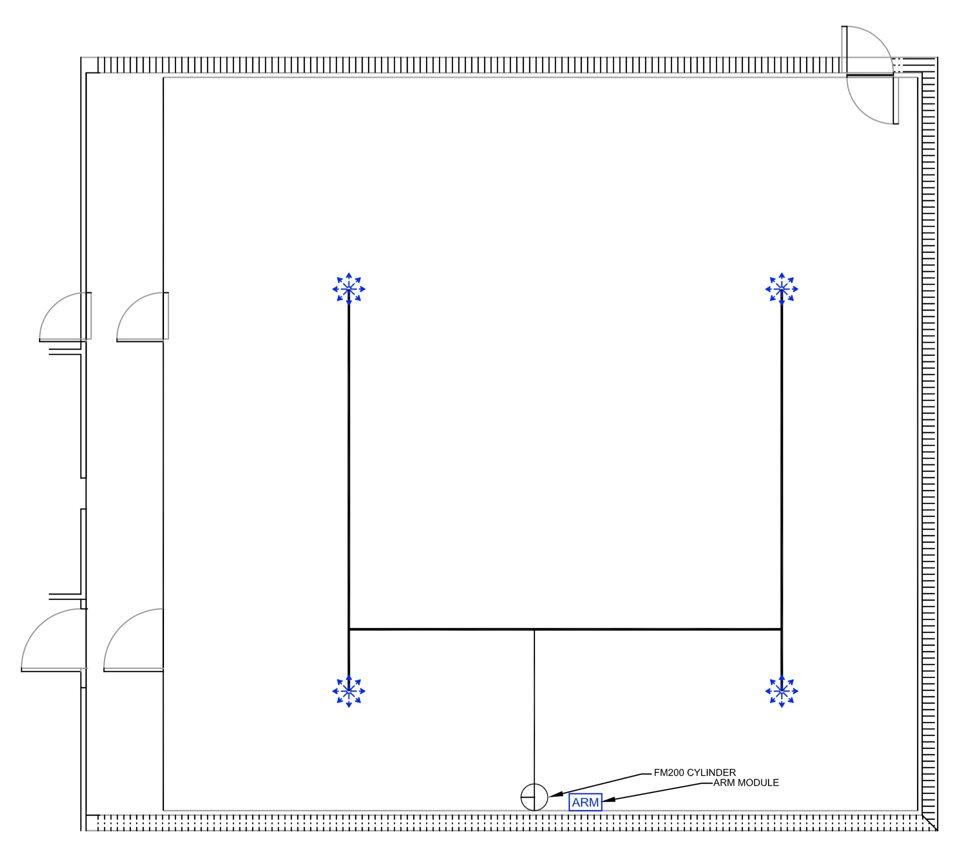
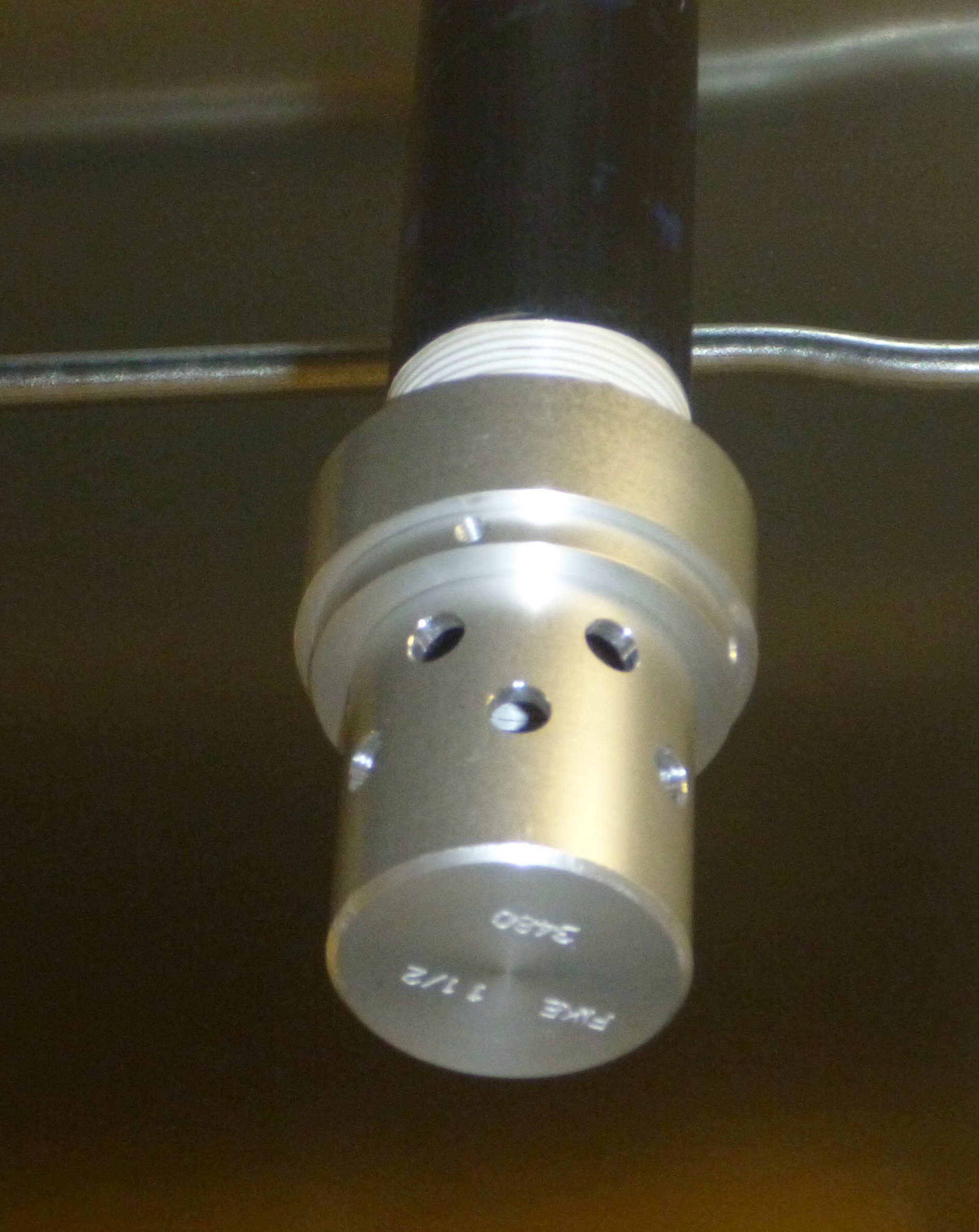
One of the FM-200 discharge nozzles. The approximate locations of the nozzles are
shown in blue in the schematic diagram above.
Other Components of Fike System
The miscellaneous other components that make up the Fike Fire Detection and Suppression system
are depictied here.
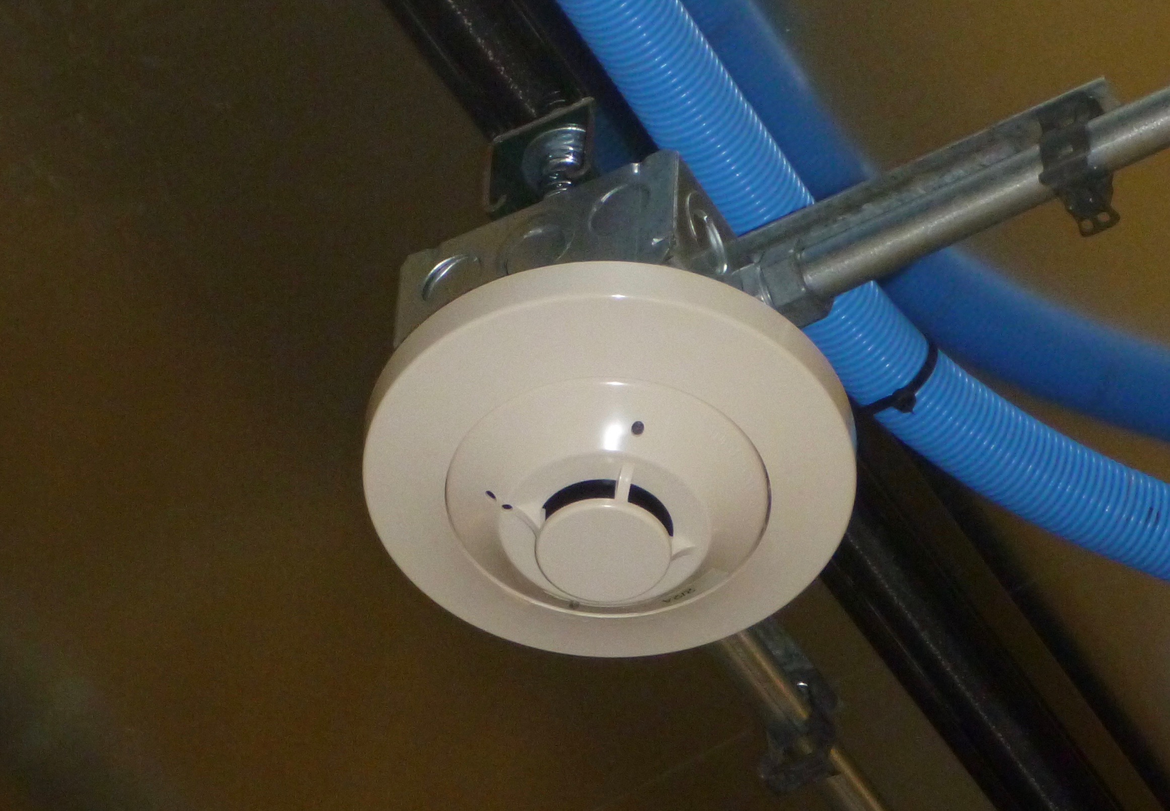
Smoke Detector
There are 9 ceiling smoke detectors and 9 subfloor detectors. Every other one is tested
every 6 months with artificial smoke; so, all 18 get tested once per year.
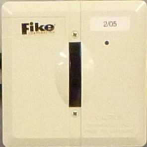
Monitor and control modules are 'addressable devices' that are used to monitor or control
'dumb' components of the system such as the flashing strobe, alarm bell, siren, FM-200
release valves, etc. They hava an infrared window that allows remote control and monitor
from a handheld remote control unit.
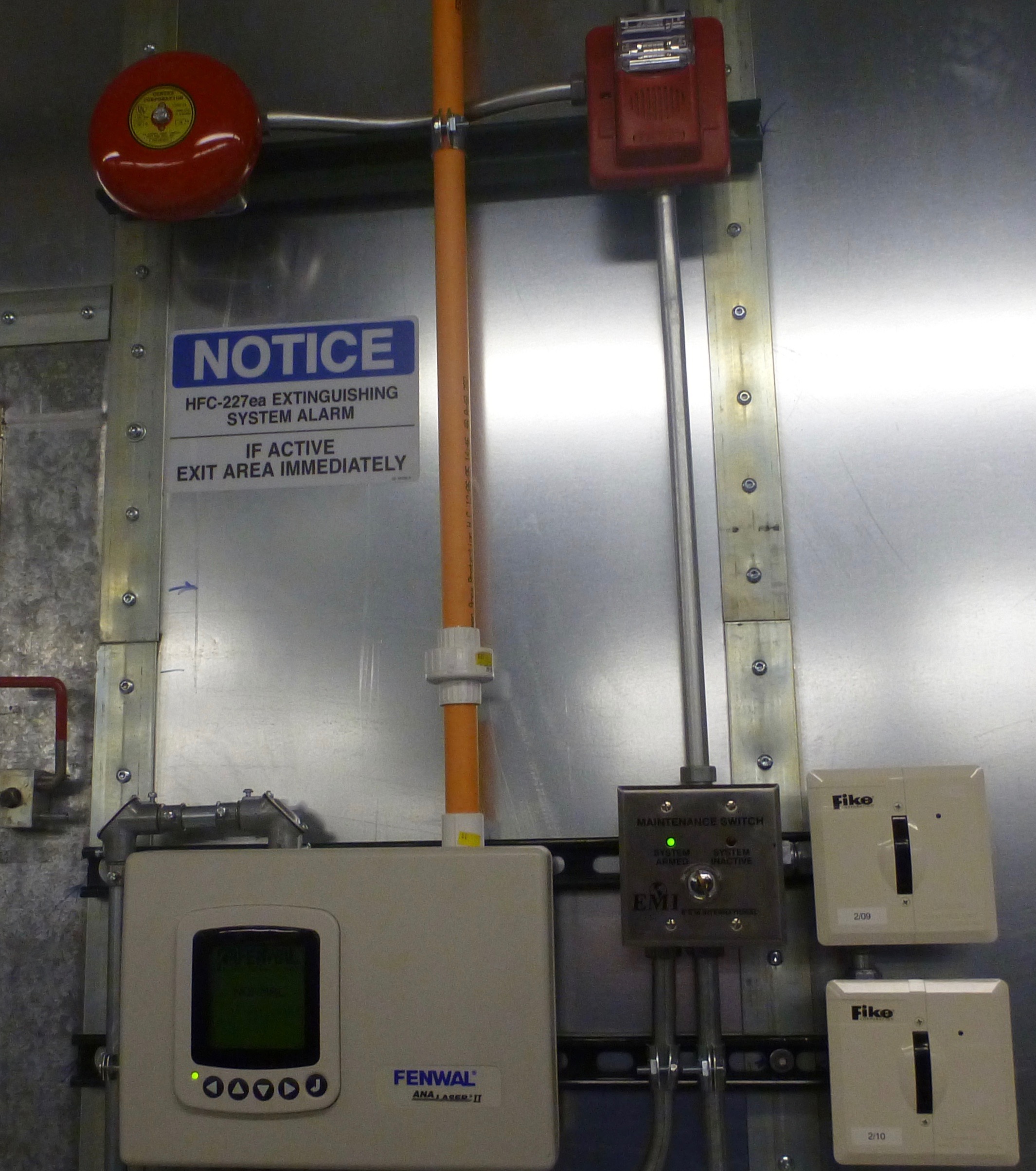
The bell and combination horn and strobe and their control modules.
The bell and the horn/strobe devices and their control modules are shown here. They are located
near the main door on the inside of the correlator room. The control modules are labeled with
their addresses: '09' is the top one that controls the bell and '10' controls the horn/strobe.
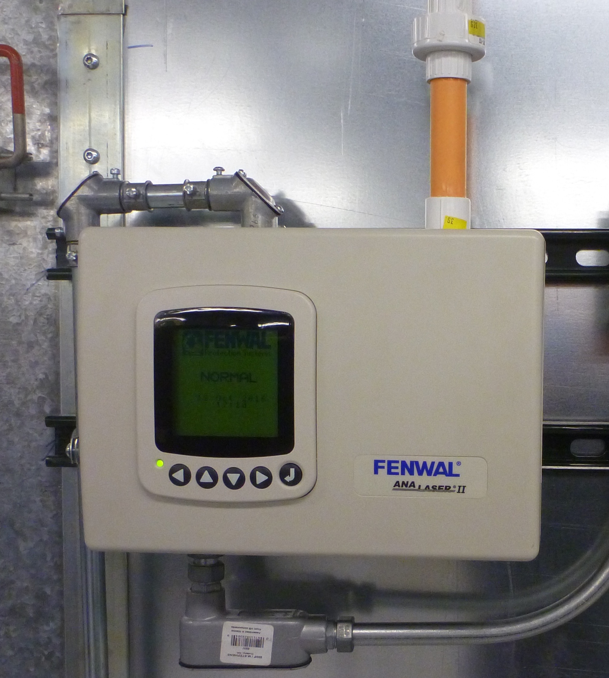
Fenwal AnaLASER II High Sensitivity Smoke Detector
Detector and Display/Control Panel
Fenwal AnaLASER II High Sensitivity Smoke Detector in the WIDAR Correlator Room.
The AnaLASER II High Sensitivity Smoke Detector used in the WIDAR correlator room consists of a
detector and display/control panel (shown above) and a piping network (described below). The
unit installed in the correlator room is the higher of two available sensitivity ranges and is
referred to as the "Ultra AnaLASER II Detector". It is capable of detecting particles of
combustion at levels of obscuration as low as 0.00015%/ft. This is sensitive enough to detect
invisible products of combustion such as the outgassing of plasticizers from overheating PVC
wire insulation and electrical components, or small changes in the ambient level of obscuration
during the incipient stage of a fire. A room that is filled with smoke so that no light may be
seen is said to have an obscuration level of 100%/ft.
Inside the box is a high-efficiency centrifigual fan that draws air continuously from the ceiling
of the correlator into a piping network and through a detector head. The detector uses a laser to
count the number of discrete particles of a specific size in a given time period.
The Detector’s particle size discrimination feature allows only a specific range of particle sizes
(between 0.01 and 10 microns) to be measured and counted as products of combustion. Anything above
or below this range is generally ignored and does not contribute to smoke signal calculations. This
discrimination band corresponds to the center of the range of all particles of combustion. Dust
particles, which are typically larger than 10 microns, are ignored.
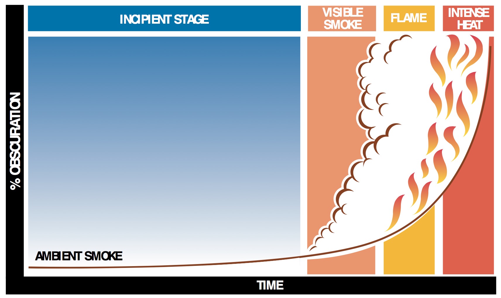
The AnaLASER detects precombustion particles at temperatures much below ignition temperature in,
what is called, the incipient stage of the fire.
When a combustible material reaches it’s ignition temperature, the combustion becomes
self-sustaining and is called a fire. At temperatures much below the ignition temperature,
chemical reactions generate airborne particles. This is typically called the incipient stage of
a fire and is followed by visible smoke, flame and finally an intense heat stage. Detection during
the incipient stage allows time for corrective action, possibly preventing an escalation of the fire
condition, and thus minimizing fire damage.
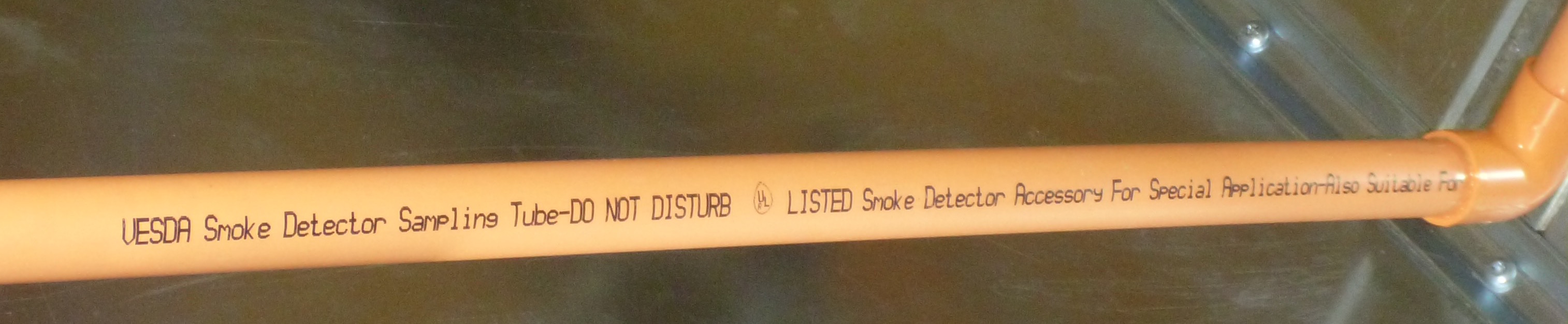
Piping
The Fenwal AnaLASER II system uses a network of 3/4" PVC sampling pipe that is run throughout
the ceiling of the correlator room. The pipe is sealed at all joints and has end caps attached
at the end of each run. Sampling ports (holes) are drilled in diameters and at intervals
determined by a software program for the specific dimensions and characteristics of the room.
The requirements for the correlator room sampling piping are:
Air sampling network piping and fittings shall be airtight and permanently fixed.
Sampling System piping shall be conspicously identified as "Smoke Detector Samping
Tube. Do Not Disturb." as follows:
At changes in direction or branches of piping;
At each side of penetrations of walls, floors, or similar barriers;
At intervals on piping sufficient to provide read visibility within the space, but
no greater than 20ft.
The approximate layout of the sampling pipe is shown in the schematic diagram at the top of
this page.
Required sampling pipe label. VESDA is an abbreviation for 'Very Early Smoke Detection Apparatus'
and has become the generic name for most air sampling applications. It is a trademark of Xtralis
Pty Ltd.
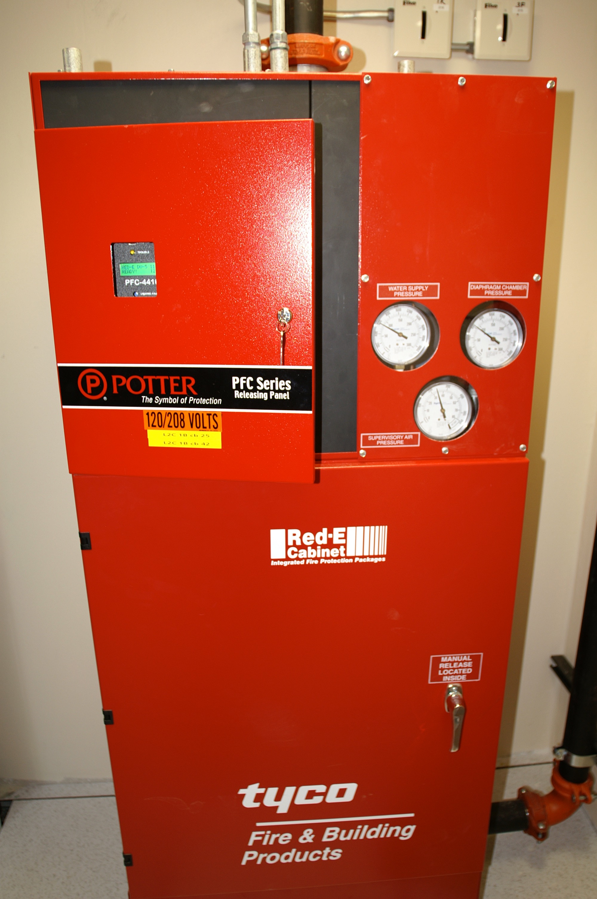
Tyco DV-5 Red-E Cabinet Integrated Deluge Fire Protection Package
The third major component of WIDAR's Fire Detection and Suppression system is the water sprinkler
system or, more formally, the preaction deluge fire protection System. This is a 'dry pipe' type
system meaning that piping to the sprinkler heads contain no water until a fire is detected.
This has obvious advantages over a wet pipe system like what was used in the old correlator room
which exhibited the natural problems of water standing in a metal pipe for 20+ years.
When a fire is detected by the Fike detection system, the Fike control box sends a signal to the
deluge system that causes water to be sent to the sprinkler heads. This does not mean that water is
discharged at that time, only that it will be ready to be discharged in the event that one or more
sprinkler heads open from heat.
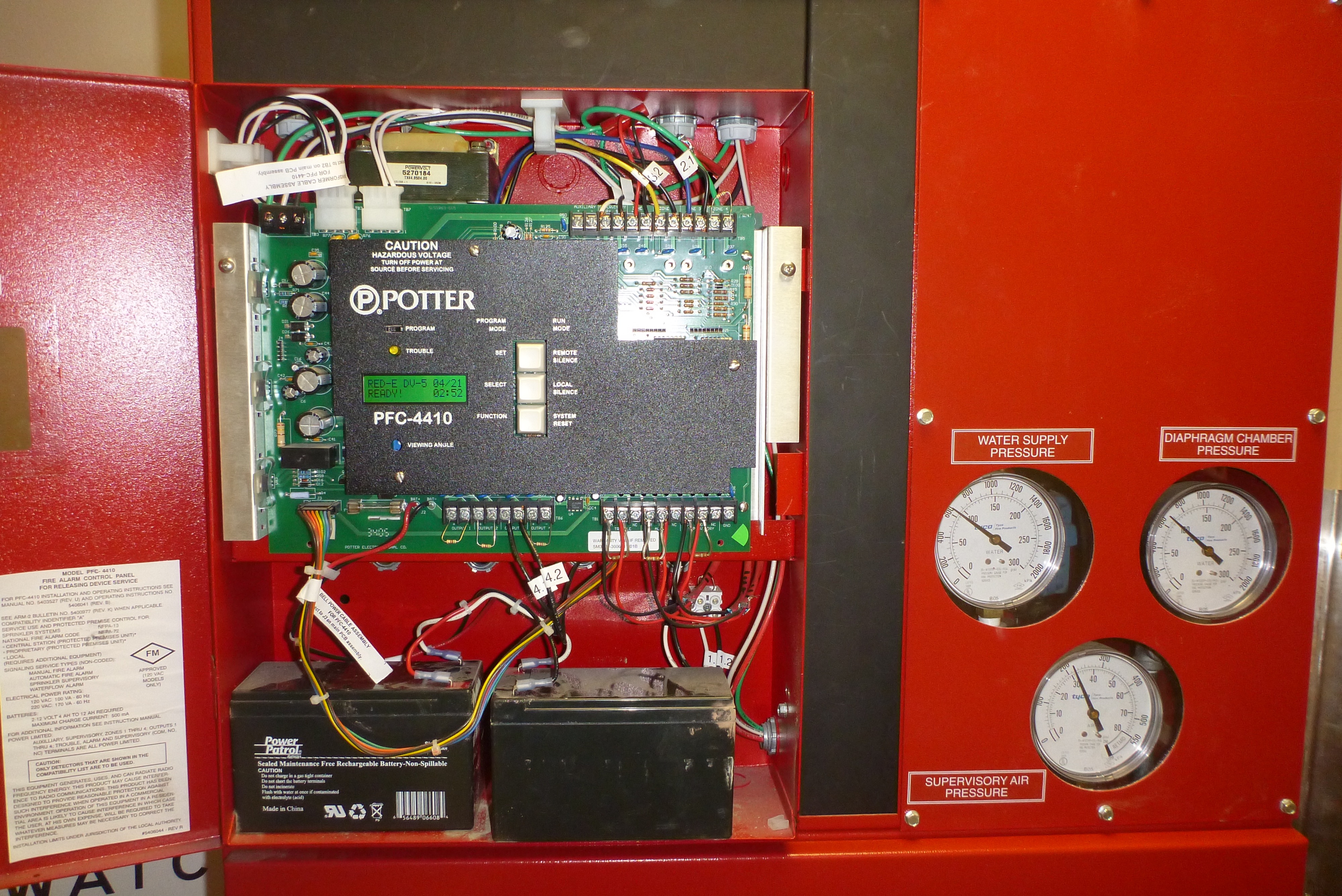
The deluge system for the correlator consist of 3 components: 1) the Tyco DV-5 Preaction Valve, 2) the
Potter PFC-4410 Control Box, each with piping and wiring, integrated into the 3) Tyco Red-E Cabinet.
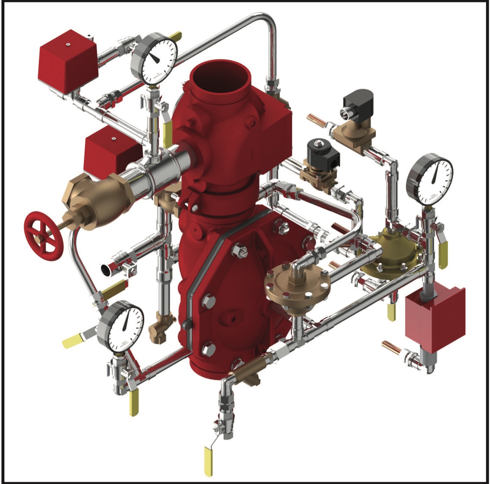
Tyco DV-5 Preaction Valve
Tyco DV-5 Preaction Valve.
The Tyco Model DV-5 Deluge Valve resides in the bottom half of the Tyco Red-E Cabinet located just
outside the correlator room near the large FM-200 Gas Tank. The deluge system is integrated into
the Fike FM200 system and is activated electrically when a second smoke detector activates (as
opposed to mechanically from the loss of pressure that occurs when a sprinkler head opens).
The DV-5 is a diaphragm style valve that depends on water pressure in the diaphragm chamber to hold
the diaphragm closed against the water supply pressure. A solenoid valve can be activated to release
the diaphragm pressure thus allowing supply water into the system. When the Fike Fire Detection system
detects a second alarm from its smoke detectors it sends an enabling signal to the deluge system's
control box which, in turn, opens the solenoid valve to allow water to flood the sprinkler system
pipes.
The Potter PFC-4410 is integrated into the Tyco Red-E Cabinet and is connected to the Fike FM200
Cheetah control box. When a second smoke detector activiates, the signal from the Fike system is
sent here and enables the deluge system. This does not mean that the sprinklers will be activated,
it only means that the system will be enabled so that if the heat from a fire is hot enough to
activate a sprinkler head, it will have water to it.
The TYCO DV-5 Red-E Cabinet is a pre-assembled fire protection valve package enclosed within
a free-standing cabinet. The entire package is pre-wired and pre-plumbed. The valve package
includes the system (manual) shut-off control valve, automatic water control valve, and
water-flow/supervisory switches.
A more complete description of the cabinet can be found here:
Red-E cabinet
< !-- alarms-action -- >
< !-- todos -- >
-->
CPCC System
The EVLA Correlator Power Control Computers (CPCC) are responsible for protecting the correlator
Station and Baseline Boards. While it is the job of the fire detection/suppression system to
protect the correlator room, and building along with the humans and equipment therein, it is the
job of the CPCCs to protect the correlator from the fire detection/suppression system. If the
correlator boards can be powered off before they are deluged in gas and water they have a fairly
good chance of not becoming damaged.
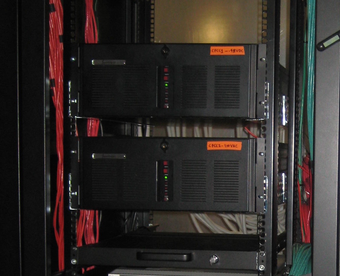
Physical Description
CPCCs are located in the auxillary equipment racks near the Southwest wall of the correlator room.
The CPCCs are a pair of SuperLogics SL-4U-SBC-CL-865G-BA. cpcc1 is powered from the correlator
room -48VDC battery through an inverter while cpcc2 is powered from the buildings AC power mains.
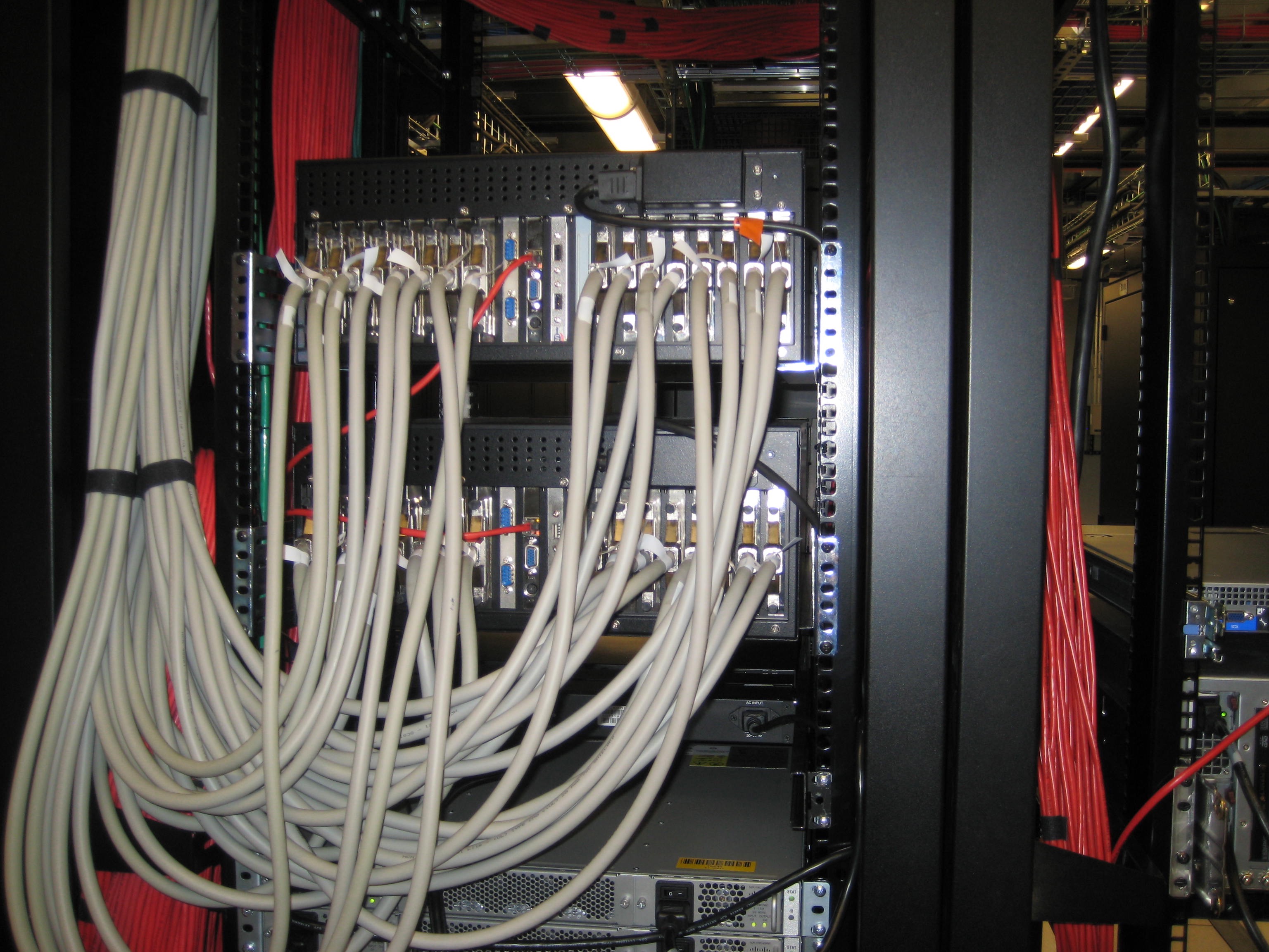
CPCCs connect directly to RPMIBs in the correlator racks via SCSI cables.
The CPCCs connect directly to the Rack Power Module Interface Boards (RPMIBs) in each of the
16 correlator racks via 100-pin SCSI cables and are also directly hardwired into the room's fire
detection and suppression system. In this manner the room could lose all network communications
and the CPCCs will still be able to monitor the fire detection system and power down the correlator
if necssary.
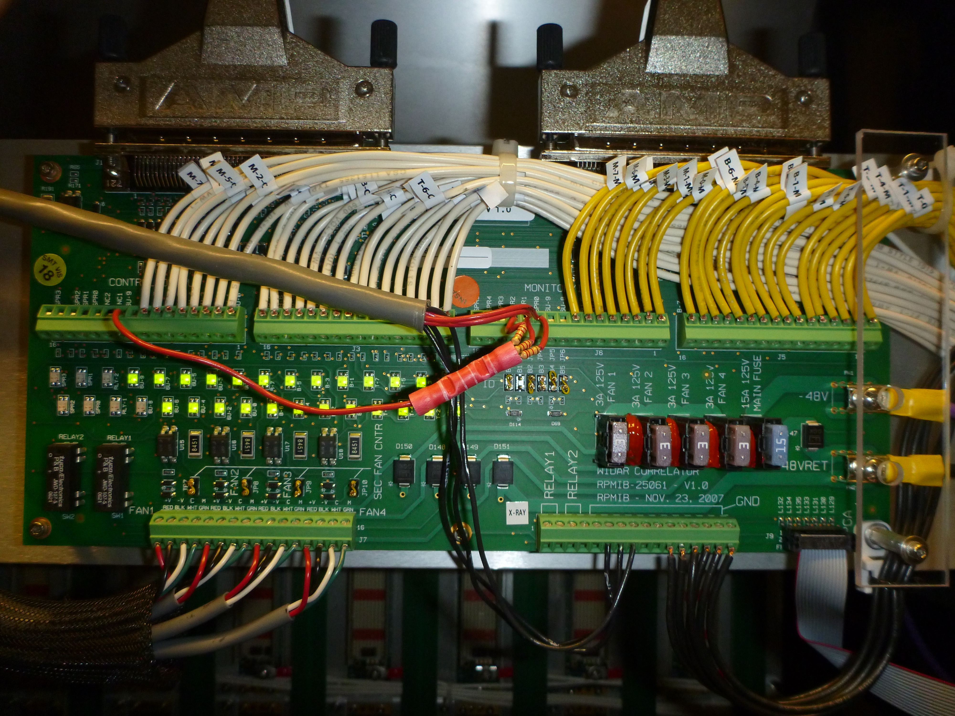
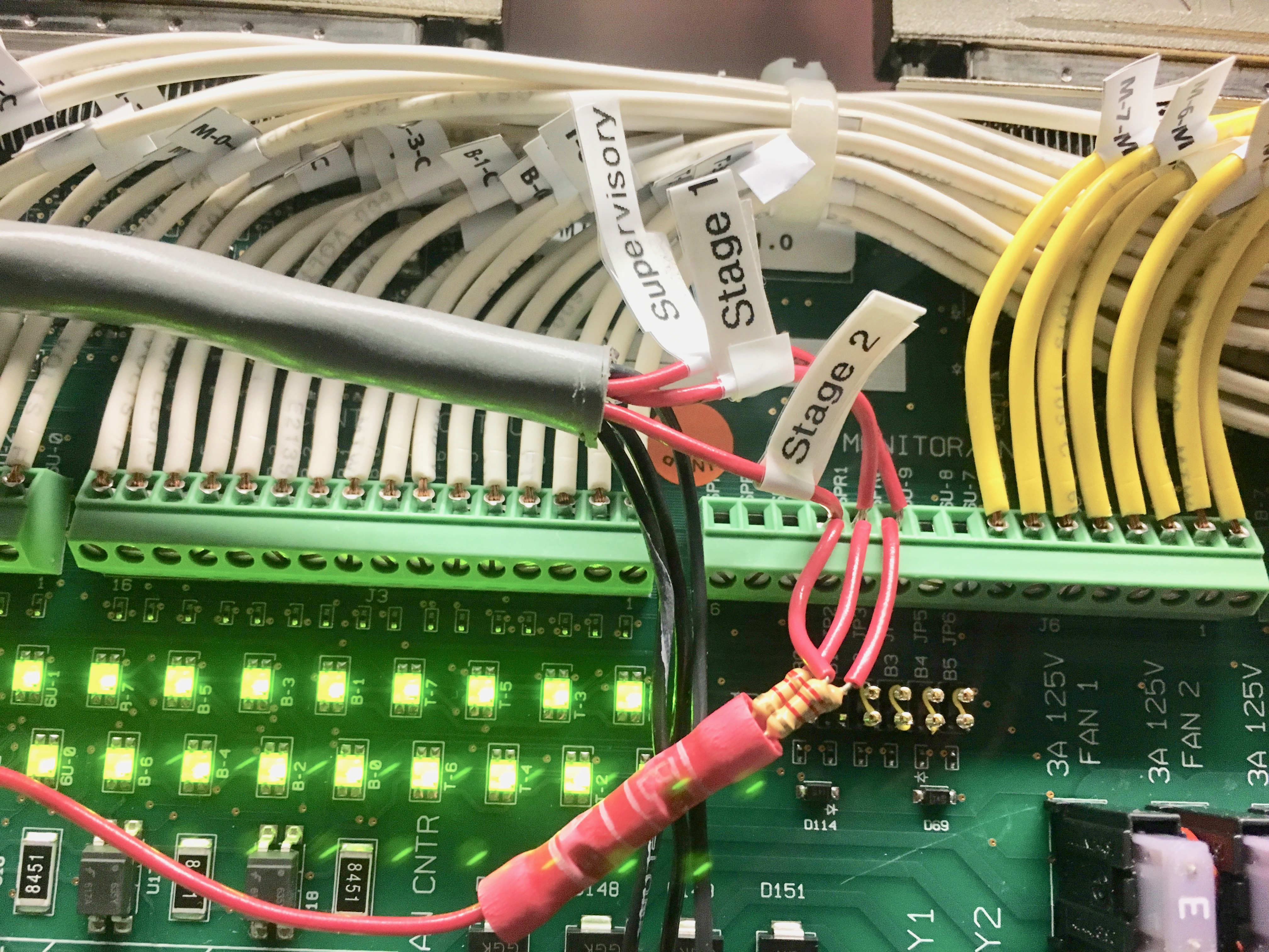
Each of the 16 correlator racks contain an RPMIB similar to this one; but this one, in Rack S002,
is the only one of the 16 that is wired into the room's fire detections system.
Three relays (in the alarm box outside the Southwest door), one for each level of smoke detection,
are wired to the RPMIB in Rack S002 (the three red/black wires in the gray sleeve). Though
deceiving In this picture, the single red line is connected to pin 6U-9. This is the TTL pullup
line for the three monitor points at SPR0, SPR1 and SPR2 (the 3 lines with the 220-ohm resistors)
for smoke alarm stages 1, 2 and 3 respectively..
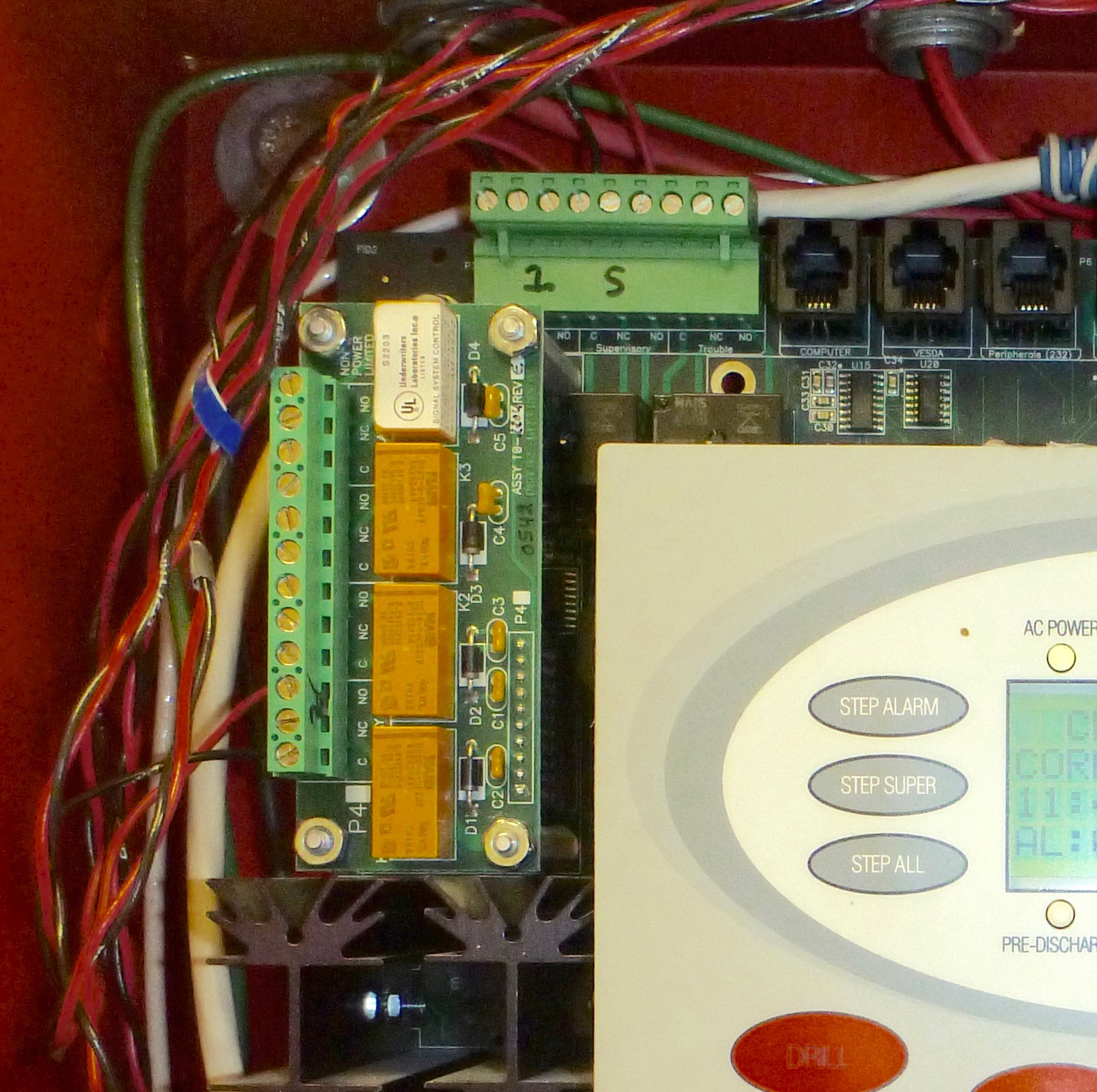
Closeup of the inside of the Cheetah Control Box showing the alarm stage relays and their
wiring connections that go to the RPMIB in Rack S002.
The Supervisory and 1st Zone alarms come from the horizontal terminal block (called P2) term
pins 6 and 3 respectively and go to the SPR0 and SPR1 pins respectively on the monitor
input terminal block on the Rack S002 RPMIB. The 2nd Zone alarm is from the installed optional
CRM-4 Relay Module (the verticle terminal module) term pin 3 and goes to the monitor input
terminal block pin SPR2 on the RPMIB.
CPCC Connection Detail Diagrams & Photos
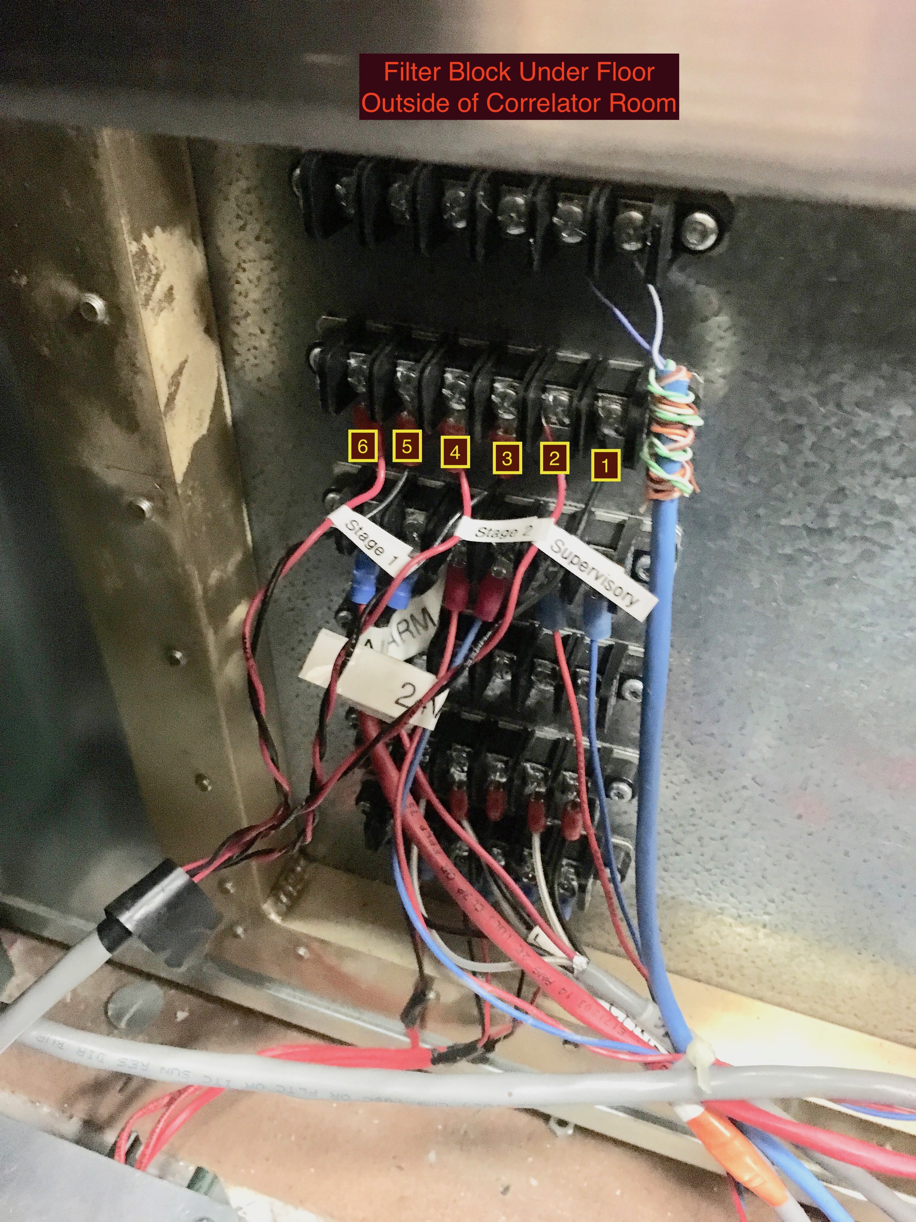
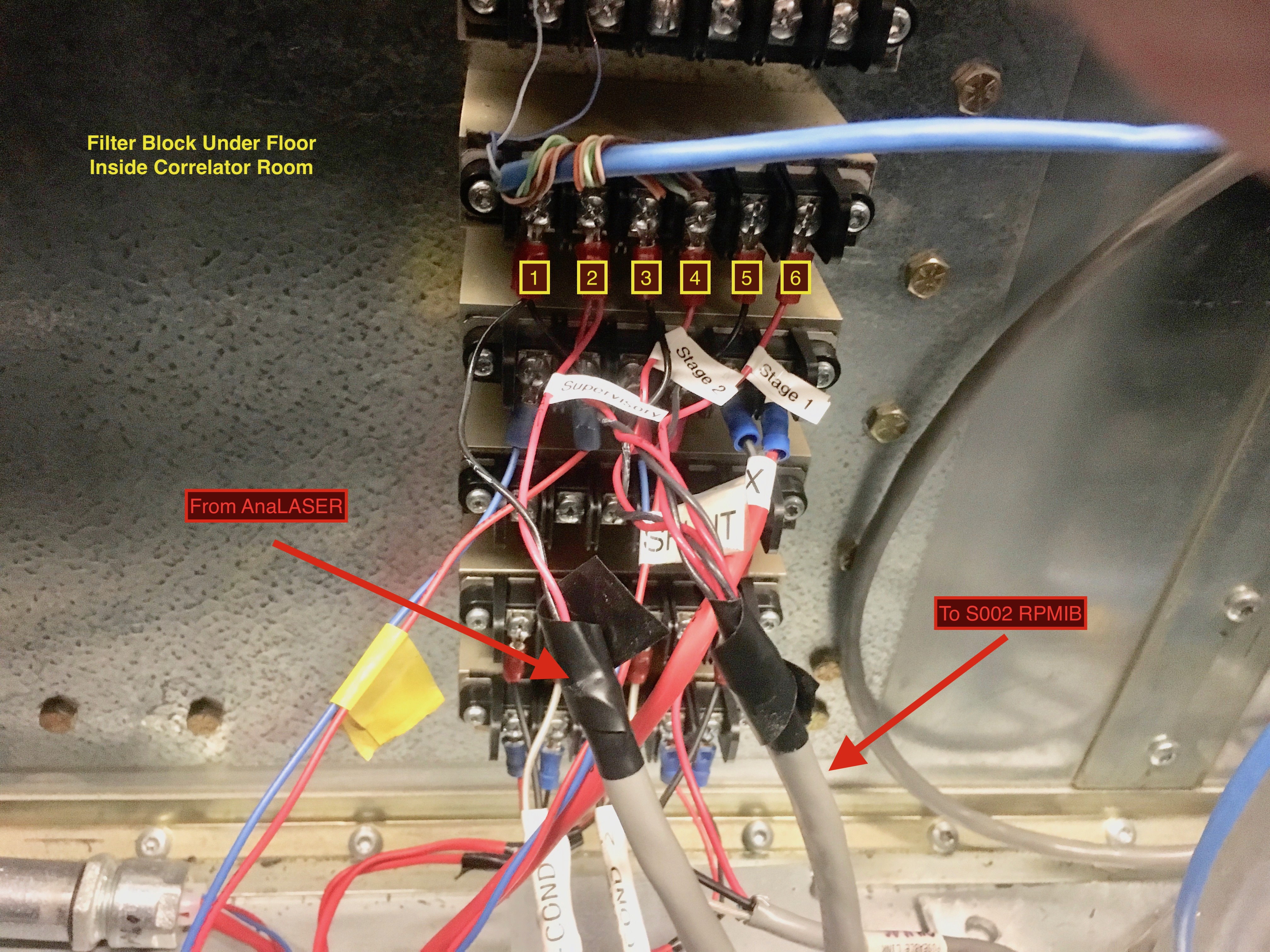
The numbered labels on the filter block are not actually present on the block,
they were added to this diagram and corresponding photos for clarity.
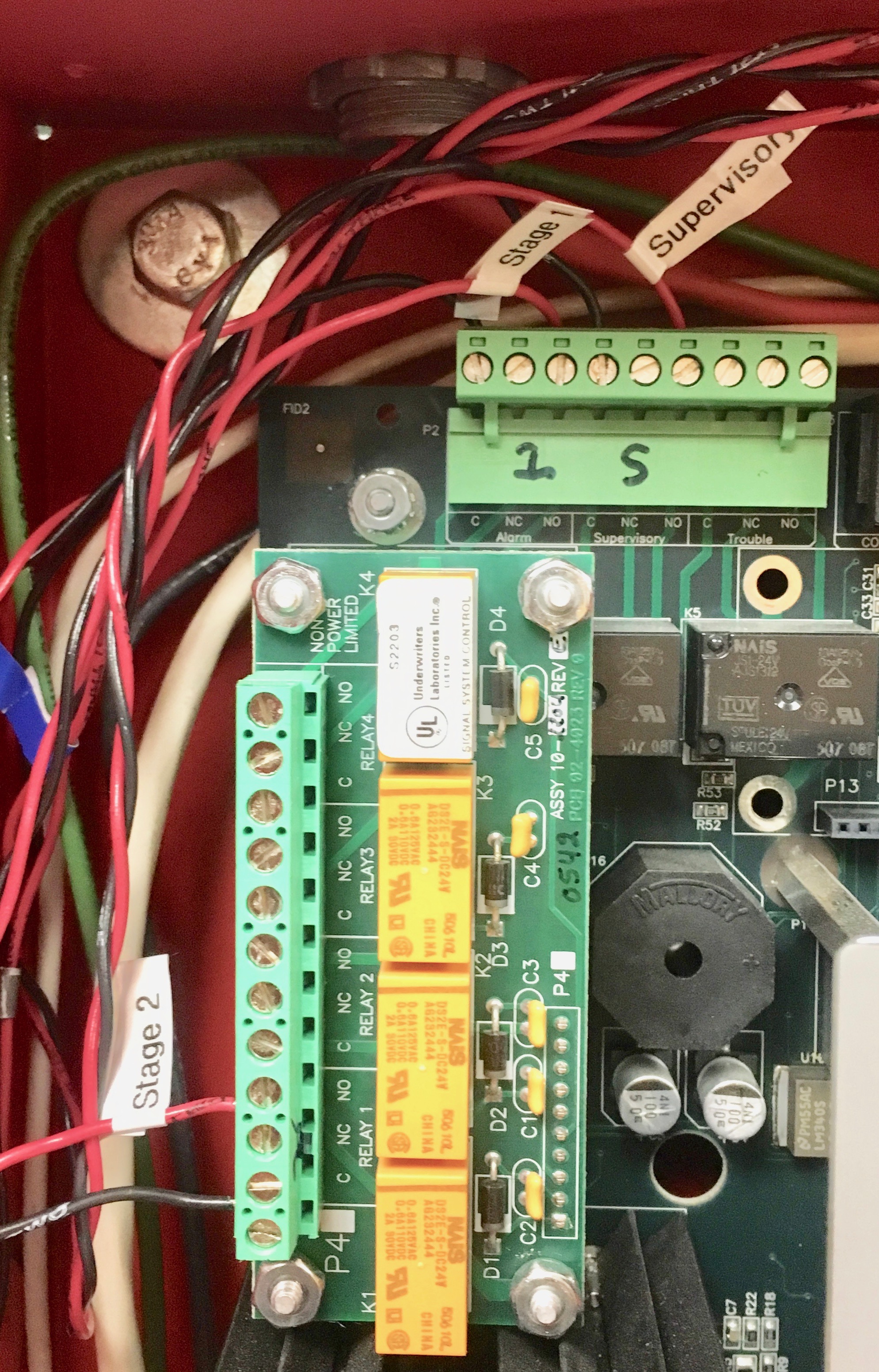
Connections inside the FIKE Control Panel. The red wires go to the Normally Open (NO)
relay terminal and the blacks go to the Common (C) terminal. When the relay energizes,
the red wire is shorted to ground.
The filter/terminal block under the floor on the outside of the correlator room under the FIKE
control panel. The wires from the FIKE panel go to here.
The filter/terminal block under the floor on the inside of the correlator room. The
connections pass straight through the terminal block from the other side of the wall.
At the RPMIB in Rack S002, the Supervisor Alarm connects to Monitor/Input SPR0,
the First Smoke Detector goes to SPR1 and the Second Smoke Detector to SPR2. The
signals are pulled up to +5VDC by the Control/Output line 6U-9 via the three
2200 ohm resistors.
Control/Output line 6U-9 must be set to a high value by the CPCC's on their initial
startup. If for any reason this line should go to a low value, the correlator boards
will be powered down. The Second Smoke Detector relay does just that; it shorts the
line to ground.
Functional Description
Two CPCCs run in parallel as peers; at least one must be running at
all times or the correlator will power off. CPCCs are wired into the fire detection and suppression
system and will power down the correlator boards to protect them in the case of sprinkler discharge;
they monitor board temperatures and regulate rack fans accordingly; they provide the mechanism for
powering up and down the system, in a staged manner, to prevent large current surges.
The CPCCs run independently and both function as 'masters' (i.e. there is no master/slave). CPCCs
constantly talk to each other over what has been called the 'MirrorLink'. They independently
monitor the system and then compare results via the MirrorLink. If one CPCC should fail the
other one resumes as normal without having to come out of a standby mode. If both CPCCs fail
to where the board power-on signals go off, all correlator boards will be powered off. This
was designed as a fail-safe mode.
Portion of the Operator's CPCC GUI showing the smoke alarm panel.
The CPCCs are wired into the fire detection/suppression system's main control panel which sends
relay closure signals to the CPCCs for each of the three alarm stages. In addition to the
appropriate LED lighting on the Operator's GUI Smoke Alarm Panel, a message will be displayed
in the message box area of the GUI:
*** Stage X Smoke Detection *** where 'X' is '1', '2' or '3'. This is followed
by a status message indicating that no automatic CPCC action will take place for stage 1 and 2
alarms and what action the CPCCs will take if it is a Stage 3. The Stage 3 action depends
on the setting of property called cpcc.initiating.system.shutdown.on.stage3.smoke
as follows:
cpcc1 : if cpcc1 detects stage 3 it initiates shutdown on both itself and cpcc2
(via the MirrorLink). If cpcc2 alone detects stage 3, nothing happens.
cpcc2 : if cpcc2 detects stage 3 it initiates shutdown on both itself and cpcc1
(via the MirrorLink). If cpcc1 alone detects stage 3, nothing happens.
neither : nothing happens
either : if either cpcc detects stage 3 it initiates shutdown and commands the other
to do likewise via the Mirrorlink.
both : the cpcc that detects stage 3 initiates shutdwon on itself only. If both
detect stage 3, the system will shutdown; if only one detects stage 3, the system will
remain up (it takes both cpcc's to shutdown the system).
For smoke alarm testing BOTH CPCCs must have their
cpcc.initiating.system.shutdown.on.stage3.smoke property set to
neither to avoid shutting down the correlator during testing. When testing is
complete, the value must be set back to either
The procedure for setting this property to disable/enable automatic shutdown is under the
control of the VLA Operators.
CPCC Fire Detection System Software Description
A Java class in the CPCC software package called SmokeDetector is an
independently running Java Thread that monitors the Rack S002 RPMIB monitor inputs
that are wired into the fire alarm control panel. It polls these inputs at a rate
determined by the property cpcc.rate.acquire.status.smoke which is
currently set at 1 second.
The polling is done through direct wiring between the CPCCs and the RPMIB and does not
depend on the Ethernet network being operational.
Contact Kevin Ryan for content corrections/suggestions:
kryan@nrao.edu -- April, 2017