PieTown
PANEL
MAP Adjustment
List Adjustment Plot
1. Introduction: HOLOGRAPHY: aips++
glossary
In radio
astronomy,
a method for refining the feed and panel alignment, thus for improving
the
aperture efficiency or antenna gain of a radio telescope. By scanning
an
antenna's beam over a raster around an unresolved radio source, and
using
another antenna pointing at the same source as a reference,
information
is obtained about the amplitude and phase distributions of the signal
reflected
from the antenna surface. These distributions are used to specify
corrections
(if needed) for the focus and alignment of the feeds or of the
positions
of individual panels in the reflector.
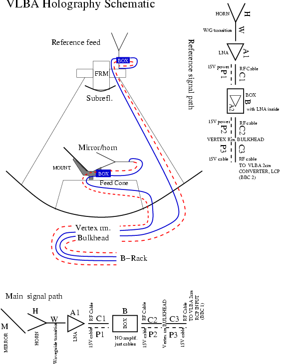
For the VLBA, there is no reference antenna nearby, as there is for the VLA in D-array. The scheme used currently is to track a geostationary satellite beacon of very narrow bandwidth (0.7Hz : here is a spectrum), and so get sufficient SNR with a small reference horn mounted on the 25m antenna.
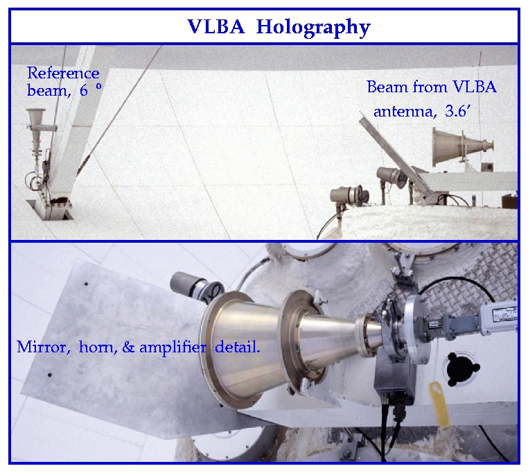
The main antenna signal is picked off above the feed-cone by a mirror & horn, so as to leave the regular set of feeds undisturbed. The 2 signals go into the VLBA 2cm downconverter, and are mixed down to ~10KHz and filtered by the BBC's to 62KHz bw. External filters cut the bandwidth to 12.5KHz. The signals are then digitized at 25KHz with 12bits, transformed by a 32K FFT, and cross-multiplied to make a software FX correlator running on a low-end PC. The PC also logs az/el offsets from the VME antenna computer. Mike Revnell designed and built this in short order.
A 4-hr
raster of +- 1.2 degrees gives about 0.7m resolution on the primary
dish surface. The same PC is used to correct for phase and
pointing drifts, and transform
the beam
pattern
into the aperture amplitude and phase distribution with the AIPS task HOLGR.
2. SCHEMATIC and gory details are in this CHECKLIST.
3. Pictures:
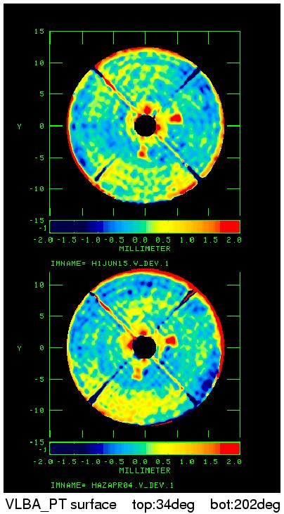
Old hardware,
with reference horn mounted on quadrupod leg, was used for
these
surface-error maps of
VLBA_PT
.
The 2 images correspond to subreflector positions over the 3mm feed
(202
deg) and almost
diametrically
opposite (34 deg). Note the 2 main reflector panels
up ~2mm
for testing.
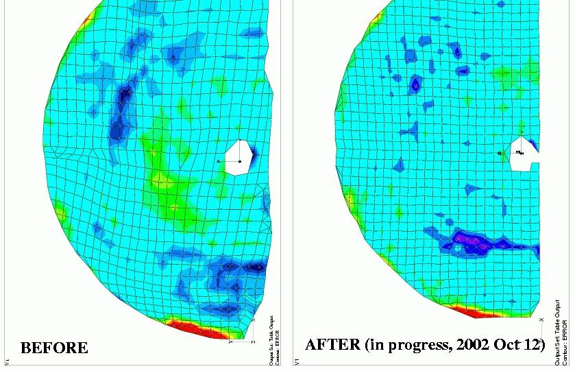
New feed-mounts
were installed 2002 March 13, allowing rotation position every 20
deg.
The reference
feed was also moved closer to the antenna
axis,
but behind the subreflector.
Repeatability is now about 100
microns,
seen in these surface maps
Here is a table
of antenna efficiencies and surface errors, to be filled as
holography visits the antennas.
4. A parallel effort to
measure and re-surface the subreflector surfaces is headed by Jon
Thunborg at the VLA antenna barn.
Measurements and resurfacing on the spare subreflector are in progress
. (Report, 2002 Jul 22 VLBA test meeting by Thunborg.)