|
|
|
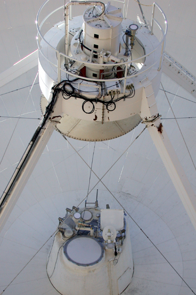 |
Shot from ground, loking into dish which is tipped down.
Reference horn is 1m away from the axis, (at top right) just outside the rotating drum that holds the subreflector - see last picture Signal path for main antenna (horn+mirror above feed cone) is
pretty much the same as before, except for the rotatable mount - see next
2 pictures
|
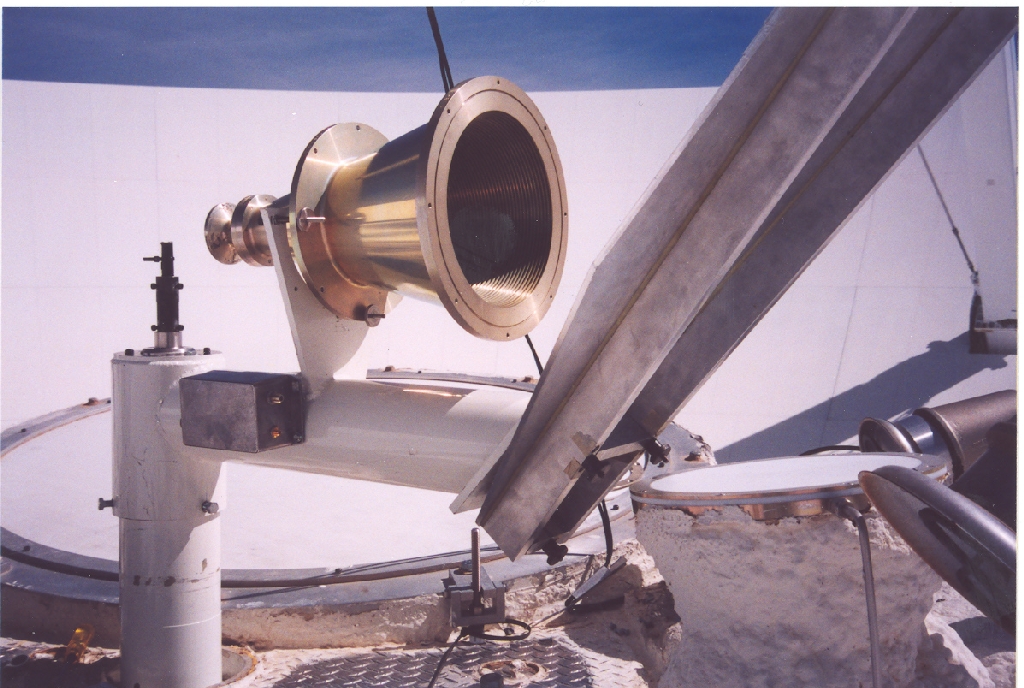 |
New rotatable mounting arrangement, note laser pointer (black finger poking up) to align the mount with antenna axis. A similar laser mounts in the horn throat, and reflects off a bit of (optical) mirror taped to the RF mirror to align the horn axis on the cross hairs of the subreflector. The typical colimation offsets for this feed are a few arcmin, not much more than those of the regular VLBA bands. Rotation and focus must be re-found if the mirror is rotated, and probably should be verified each time regardless. |
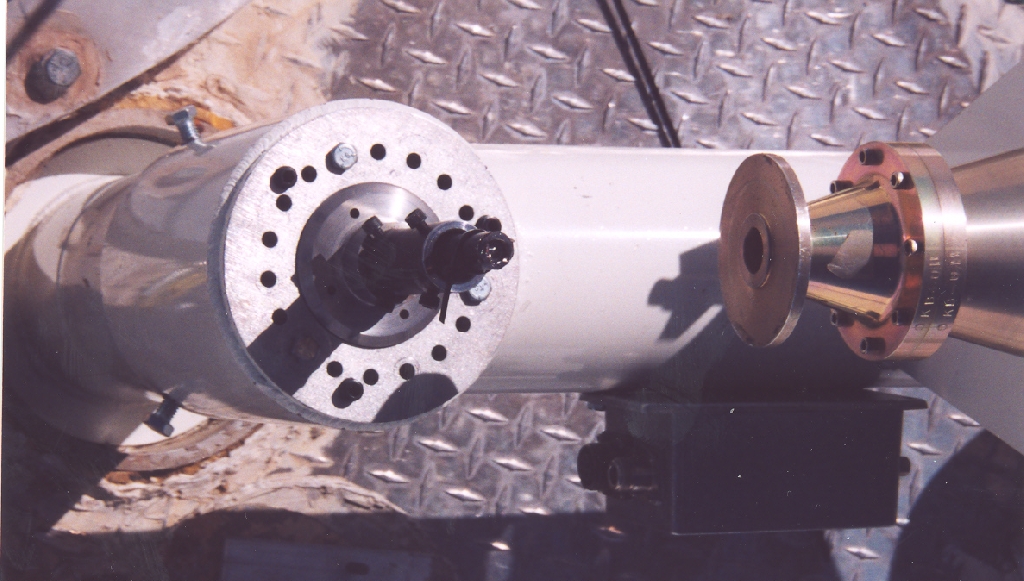 |
Top view of mount - holes every 20deg.
The orientation (linear polarization angle) of the LNA must be rotated for each position used around the feed circle to receive the linear polarization emitted by the satellite beacon (12.198GHz, vertical polarization at parallactic angle -10deg for the GE-4 satellite) |
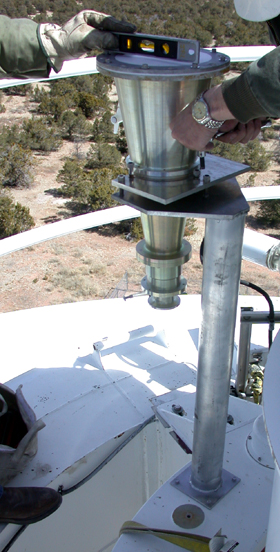 |
Reference horn position is now at the apex behind subreflector.
To align, put antenna at elevation=90 and use a spirit level on top
face. Note that the amplifier orientation and
feed alignment need not be adjusted once they are optimized for a given satellite. |