Lecture 18 - Telescopes (2/23/96)
Seeds: Chapter 5
- Some details ...
- New office hours: Mondays 3:30-4:30 and Thursdays 2:00-3:00 PM in
my office (DRL 2N3C).
- Homework #3 is now due on
Monday 2/26/96 instead of today. Note that the
web version has some
clarifications and hints.
- Homework #4, handed out today,
is due on Monday 3/4/96.
- The updated course schedule
reflects the new weekly homework scheduling, and the new reading
schedule.
- Next week we will cover Chapter 6 and hopefully start Chapter 7.
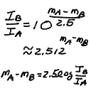
- I noticed on the midterm that many of you were confusing the factors
of 2.5 and 2.512 that appear in the intensity - magnitude relation.
Note that the 2.512 is actually 10^(1/2.5) or 2.5 = 1/log(2.512)
approximately (the 2.512 is rounded). The 2.5 is exact, in the
relations I_A/I_B = 10^( m_B - m_A / 2.5 ) or
(m_B - m_A) = 2.5 log(I_A/I_B) (see below).
- Images from Lenses and Mirrors
- A lens can be made from a refracting material such as glass that
is shaped with oppositely curving surfaces such that parallel light
rays passing through from one side are focused to a point, called
the focus, on the other side of the lens.
- The distance from the center of the lens to the focus is naturally
enough called the focal distance, which we will abbreviate
as f.
- Note that the focus is on the line running through
the center of the lens perpendicular to the plane that bisects
the lens - this is called the optical axis.
You can make a good lens out of two spherical surfaces,
where the radius of curvature determines the strength of bending
and thus the magnification. The useful lenses for our purpose are
converging lenses, with convex surfaces so that the rays
pass through and converge. If you make a lens with concave surfaces,
the rays will diverge, which isnt too useful here!
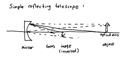
- You can focus rays also with a curved mirror. It turns out that
a parabolic mirror (shaped like a parabola) will focus incoming
parallel rays also to a point along the optical axis. Note that
the focus is of course in front of the mirror.
- The reason we consider parallel incoming rays is that we are most
interested in looking a very far away objects like planets and stars.
These objects are so far away that the light rays from them are
essentially parallel by the time they reach the Earth.
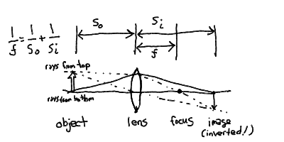
- It is interesting to look at the image formation with a lens or
mirror. Just by drawing an upright object, like an arrow, with
the bottom on the optical axis some distance in front of the lens,
then drawing the rays, we can see where an image is formed. You
only need to know that rays parallel to the optical axis are bent
to pass through the focus, and that rays through the center of the
lens are not deflected.
- You find that the image is inverted (upside down!) and located
some distance beyond the focus which depends upon the how far in
front of the lens you drew the source, and how strong a lens you
made it (what the focal distance was).
- There is a thin-lens equation that states:
1/f = 1/s_o + 1/s_i
where s_o is the distance from the source object to the
lens, and s_i is the distance from the lens to the image
(and f is the focal distance).
- Note that if you move the object out to infinity in front of the
lens, then the image moves closer to the focus. Thus, for
astronomical purposes, the image of a distant star-field is
made in the focal plane, the plane perpendicular to the
optical axis and containing the focus.
- You can make the same exercise for the parabolic mirror. You also
find an inverted image that moves closer to the focal plane as you
move the object to infinity.
- In both cases for a single lens or mirror the image is inverted.
Note that our eye is a single lens, and thus we see the world upside
down (at least on our retina). Our brain has been trained from birth
to ignore this and reprocess the information so that we perceive the
world as right side up! Part of the fumbling about by little babies
is learning to deal with inverted images in the eye. The optical
processing by our brains is trainable - scientists have done
experiments where special goggles that invert our view are worn by
subjects, who of course are disoriented at first. After a few days,
they find that they see the world not upside down but right side up
again! This reverses when they take off the goggles, and their
vision is returned to normal.
- Refracting & Reflecting Telescopes
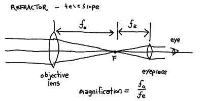
- You can make a simple refracting telescope by placing a large
objective lens at the top of a tube, and then a second
smaller lens called an eyepiece at the bottom end of the
tube. The eyepiece is place just beyond the focus and its
purpose is to focus the diverging rays into parallel rays again,
which are then focused by our eyes just as if we were looking at
the sky without the telescope.
- The focusing of the eyepiece controls the size of the image
that appears on the eye, and thus the magnification of the
telescope (see below).
- Note that a refracting telescope, or refractor is unwieldy
to make, since you need a long tube for big lenses (since its hard
to make large strongly curved lenses). If you've picked up a
large magnifying glass, you also know big lenses are very heavy!
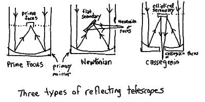
- You can make a reflecting telescope, or reflector, by
placing a parabolic mirror at the bottom of a tube. The focus is
then inside the tube, unless you put a second mirror in front of
the focus to direct the light somewhere else.
- The large main parabolic mirror in a reflector is called the
primary mirror, and its focus inside the tube is called
the prime focus. Many large optical telescopes are big
enough so that there is actually room inside the tube for a person,
who can observe at the prime focus (with an eyepiece)! Many radio
telescopes put their receivers at prime focus also.
- If a second mirror, or secondary mirror is placed in front
of the prime focus, and is oriented at 45 degrees to the
optical axis so as to reflect the light through
a hole in the side of the tube, then we have what is called a
Newtonian telescope, with a focus on the side and outside
the telescope called the Newtonian focus. This is the
first sort of reflecting telescope built 1668 by Isaac Newton
(designed in 1663 by James Gregory).
- If you orient the secondary mirror perpendicular to the optical
axis, then the converging rays are pointed back down toward the
primary. If a small hole is made in the center of the primary,
then the focus can be place at the bottom end of the telescope
where it is very convenient for observing. This design is known
as a Cassegrain telescope, and the focus is of course
the cassegrain focus.
- With extra mirrors, there are an number of different configurations
where the focus is directed to convenient places outside the tube.
See the textbook for some of these.
- Note that both for refracting and reflecting telescopes, the image
quality degrades (becomes distorted and blurry) as you look at stars
that are at increasing angles from the optical axis. This is because
the simple lens or parabolic mirror only has a point-like focus for
rays parallel to the optical axis - rays at slight angles actually
focus into a little blurry spot that gets bigger the further you
go off-axis. Thus the useable field-of-view, the angle from the
center of the image that is not terribly distorted, is fairly small
for these telescopes.
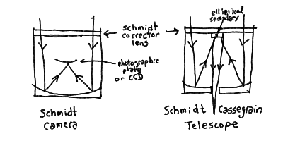
- For a refracting telescope, complicated lenses with different surfaces
and extra lenses can be used to "correct" for these aberrations.
For a reflector, the secondary mirror can be specially figured and
a large thin correcting plate or lens can be placed at the top of
the tube. If this is done to a Cassegrain telescope, then it becomes
a Schmidt-Cassegrain telescope (the lens is called the Schmidt
corrector). This is the most popular sort of serious astronomical
telescope.
- Note that if a Schmidt corrector is place on a prime-focus telescope,
you get a telescope with an excellent wide field of view. If you
place a photographic plate or other detector at the prime focus, then
you get a Schmidt Camera. These are used to make sky surveys,
with a single photographic plate that covers as much as 6 degrees!
- The Powers of a Telescope
- Three "powers" of a telescope:
- Light Gathering => brightness of images
- Resolving => sharpness of images
- Magnifying => size of images
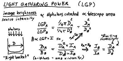
- Light Gathering Power (LGP) is a measure of the ability
of the telescope to collect light energy and concentrate it
into the image or detector. Each photon of a given frequency
f carries a quanta of energy h f, so the total
energy collected is proportional to the number of photons collected,
which in turn is proportional to the area of the primary mirror or
objective lens of the telescope. Think of a telescope as a big
"light bucket" collecting a rain of photons. Since the area
of a telescope of diameter D is proportional to D^2, the light
gathering power LGP is proportional to D^2. Note that LGP is
really only useful as a ratio between two different telescopes.
If a quantitative measure is needed, the telescope area
A = Pi D^2 / 4 is used.
- The brightness B of an image of a source of intensity I
for telescope area A is given by B = A I.
- Two telescopes looking at the same source (same intensity) form
images of brightnesses given by the ratio of the areas.
- Two telescopes forming images of the same brightness are looking
at sources with ratio of intesities given by the inverse ratio of
areas.
- The Resolving Power of a telescope is a measure of the sharpness
of the detail that can be seen in an image made by the telescope.
Strictly speaking, it is the degree of angular localisation of the
light on the sky coming from a single point source - that is, the
degree of "blurring" that occurs for a source of infintesimal angular
size (like a star for most telescopes).
- The resolution of a telescope is the angular diameter of the
blurred disk of a point source, and is usually measured in arc-seconds.
Thus, the resolution is also a measure of how close two astronomical
objects such as stars can be on the sky and be seen as distinct.
- The reason the image is blurred by the telescope is because the
waves corresponding to the photons being collected by the telescope
are being cut off by the finite size of the collecting mirror or lens.
We need the wave nature of light to understand this effect (known as
diffraction).
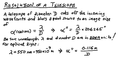
- It turns out (see next lecture), that the resolution (in radians) is
just the wavelength divided by the diameter of the dish (in the same
units, such as meters) - see the panels below. For resolution in
arcseconds, we multiply by the usual factor of 206265 arcsec/radian.
- Note that for optical light, with a representative wavelength of
550 nm for example, a 1-meter diameter telescope has a resolution of
0.116 arcseconds.
- Larger telescopes have better (smaller) resolution, and can distingish
things that are closer together as well as show finer detail on
extended sources.
- However, the Earth's atmosphere causes its own blurring, limiting
ground based telescopes, even those on high mountain tops, to a
resolution of about 0.3 to 1 arcseconds for visible wavelengths of
light. Thus, from the ground,
the resolution of a telescope of diameter greater than about 0.3
meters is limited by the atmosphere, not its size, at optical
wavelengths.
- To obtain better resolutions than this, we must put our telescope
above the atmosphere in space or on high-flying aircraft.
- The other power of a telescope is magnifying power, or
the size of the image produced by the telescope. This depends upon
the focal length of the primary or objective f_o,
and the focal length of the eyepiece or any re-imaging optics
f_e. The magnification is given by the ratio of the
two, m = f_o/f_e - this is how many times larger
an image appears than if you just looked with your eye alone. Since
it can be changed simply by changing the focal length of the eyepiece,
it is the least important of the powers.
- Telescopes of the World
- There are a good number of powerful telescopes now operating
around the world. Below is a quick survey of some of the best
of these. You can also explore the internet on your own by
using your favorite Web searching engine using "telescope" or
"observatory" as a keyword (try
this).
- Although most optical telescopes operate alone as a single (often
large) telescope, some radio telescopes are linked together to
form what are called interferometers, or
interferometer arrays.
- An interferometer array is like one large telescope made up of
smaller telescopes - it has the resolution of a single telescope
of a diameter equal to the largest distance between two telescopes
in the array, but has the light gathering power of the sum of the
collecting areas of the individual telescopes (usually much less than
the area of a single telescope the size of the array). Thus, an
interferometer can give superb resolution for even modest size
telescopes.
- It is difficult to link an interferometer together. You need to
adjust things to a fraction of a wavelength. This is easiest in
the radio part of the spectrum, where wavelengths range from 1 mm
to 1 meter. In the optical, with wavelengths of 1000 nm or less,
this is extremely difficult as you might imagine! There are several
groups of astronomers around the world working on this important
technological problem.
- For more on interferometers, see the
next lecture.
Next Lecture -
Atoms and Starlight
Some details ...
Images from Lenses and Mirrors
Focusing in a single thin lens:
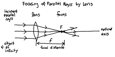
Image formation with a single thin lens, and the thin-lens equation:
Focusing with a single paraboloidal mirror:
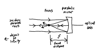
Image formation with a paraboloidal mirror:
Refracting & Reflecting Telescopes
A simple compound refracting telescope, with objective and eyepiece:
Three types of reflecting telescopes: prime focus, Newtonian, and
Cassegrain:
The Schmidt Camera and the Schmidt-Cassegrain Telescope:
The Powers of a Telescope
The Light Gathering Power and image brightness:
Resolving Power and resolution of telescope:
Telescopes of the World
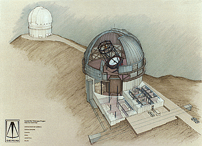
The ESO Very Large Telescope (VLT) is now under construction in Chile.

The twin 8-meter telescopes are being built the US National Optical
Astronomy Observatory (NOAO) on Mauna Kea, Hawaii and in Chile.
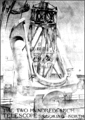
For many years, the 200-inch (5-meter) Hale Telescope at Palomar
Observatory in California was the largest telescope in the world.
It was finished in 1948. Here is a detailed construction drawing
by Russell Porter from 1938:
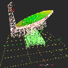
The Green Bank Telescope (GBT) is a large steerable radiotelescope
being constructed in Green Bank, West Virginia, by the National Radio
Astronomy Observatory (NRAO).
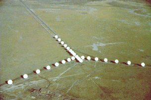
The NRAO Very Large Array (VLA) is an interferometric array of 27 antennas,
each 25-meters in diameter, placed on railroad tracks on a high plain
near Soccorro, New Mexico. This interferometer make radio images with
the resolution of a single telescope 36 km across!
The Very Long Baseline Array (VLBA), constructed by NRAO, consists of
nine 25-meter telescopes
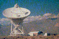
located at sites across the USA from Hawaii to
the Virgin Islands.

The longest baseline is 8612 kilometers, and the
resolution is as good as a telescope of this enormous size!
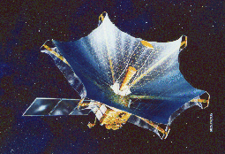
The soon-to-be-launched VLBI Space Observatory Program (VSOP), is a 8-meter
antenna on a Japanese satellite that will orbit the earth out to distances of
2.6 Earth diameters. In conjunction with ground-based VLBA telescopes, this
will give a baseline of over 33000 km!
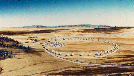
The NRAO has proposed building an interferometric Millimeter Array
(MMA) that will do what the VLA does but at shorter wavelengths of 0.3
to 3 millimeters. The current design is for 40 8-meter telescopes
arranged on a circular track in the high mountains of northern Chile.
Go to Previous Lecture ----
Go to Next Lecture
Back to the Lecture Notes Index
Back to the ASTR001/Sec3 Page
Steven T. Myers - Last revised 26Feb96


