Table of Contents
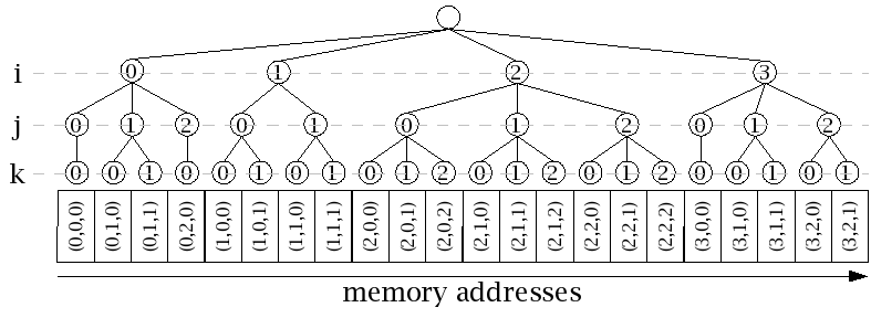
The binary tables contain the data associated with a backend integration. As the name suggests, these tables contain binary data, and remain unencoded in the MIME format. Indexing of each table can be represented by a constant height ordered tree, with fixed length data elements stored in the leaf nodes of the tree (see Figure 4.1, “Binary table index structure” for a small example). Note that, although the indexing of the binary tables assumes a tree structure, the data elements are organized in contiguous, linearly-addressed memory segments. The order of the data elements in memory corresponds to an in-order traversal of the tree's leaf nodes; that is, the indexes are lexicographically ordered.
While the tree representation of binary table indexes is completely generic, the definitions of the binary tables exhibit constraints on the number of child nodes at every level of the tree. Additionally, the constraints may be a function of the tree branch (or sub-tree) in which the nodes occur. The following sections describe the order of the axes (or tree levels) in each binary table, any hard constraints on the size of each axis, the dependencies of the size of each axis on preceding axis coordinate values (equivalently, the dependency on tree branch), and the data stored in the tables.
The following table (Table 4.1, “ Binary table index order and dependencies ”) shows all of the axes that may be present in the binary tables, their order, and allowed size dependencies. Note that the axes present in any given binary table may be a subsequence of the axis sequence shown below. An “X” in the table below indicates that the size of the axis named in that row may depend on the coordinate value of the axis named in that column. If there is no “X” in a row, the axis named in that row has a constant size in each data file. The order of the axes in the binary tables is represented below by the order of the rows from top to bottom.
![[Note]](images/note.png) | Note |
|---|---|
The axis ordering presented in this document is in the direction of descending the levels of the index tree as described above, which results in a lexicographic ordering of tree indices (which is a generalization of row-major array order). In contrast, although the ALMA document specifies the same ordering of elements in memory, the axis order presented in that document is the reverse of what is given here, which implies that the indices must be traversed in column-major order to result in an unaltered ordering of data elements. Unfortunately, because the ALMA convention is embedded in the definition of an SDM header element attribute, the EVLA schema uses the ALMA convention; however, this document describes the ordering based on the lexicographic convention because it agrees with the model presented above, is likely to be more familiar to C, C++ and Java programmers, and is consistent with an “array of arrays” implementation these programmers might use. |
Table 4.1. Binary table index order and dependencies. Abbreviations: bl, baseline; bb, baseband; sw, spectral window; pb, phase bin; ab, APC bin; sc, spectral channel; pp, polarization product.
| axis | dependence | ||||||
|---|---|---|---|---|---|---|---|
| bl | bb | sw | pb | ab | sc | pp | |
| bl | |||||||
| bb | |||||||
| sw | X | ||||||
| pb | X | X | |||||
| ab | |||||||
| sc | X | X | |||||
| pp | X | X | |||||
Whenever the integration header indicates that the size of a table is zero bytes, that binary table shall be omitted from the data stream (which means that the entire MIME part for the affected table will not be present.) This may occur when, for example, no flags are set during an integration.
| Note |
|---|---|
The ALMA document discusses the occurrence of optional tables in the data stream (dependent upon the correlator in use), but such tables never occur for EVLA. |