


Next: Bootstrapping for antenna gains
Up: Procedure for extending uv-limit
Previous: Procedure for extending uv-limit
A Radio interferometer samples the spatial coherence function of the
radiation field as a function of the baseline (projected antenna
separation measured in the units of wavelength). These measurements,
called the Complex Visibilities ( ) can then be Fourier
inverted under suitable assumptions to make the raw map of the
corresponding radiation field. However, the observed visibilities
(
) can then be Fourier
inverted under suitable assumptions to make the raw map of the
corresponding radiation field. However, the observed visibilities
(
 ) as measured by the interferometer needs to be calibrated to recover the true visibilities (
 ). In the
absence of any systematic baseline based offsets true visibilities are
related to observed ones as
). In the
absence of any systematic baseline based offsets true visibilities are
related to observed ones as
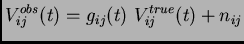 |
(1) |
where  and
and  are the baseline based complex gains and
noise respectively. A very straightforward way to recover the true
visibilities would be to look at a standard calibrater and determine
the s i.e. baseline-based calibration. For various reasons
antenna-based calibration is preferred over this method(see section
7.5 of reference 1).
are the baseline based complex gains and
noise respectively. A very straightforward way to recover the true
visibilities would be to look at a standard calibrater and determine
the s i.e. baseline-based calibration. For various reasons
antenna-based calibration is preferred over this method(see section
7.5 of reference 1).
In the antenna-based calibration scheme,  is modeled as the
product of two antenna-based complex gains:
is modeled as the
product of two antenna-based complex gains:
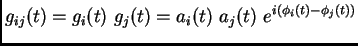 |
(2) |
where  is the antenna based amplitude correction and
 is the antenna based phase correction. These are
traditionally determined from observations of an unresolved
source. However at low frequencies many of the VLA calibrators show
extended emission. Hence, they are not usable as the phase-calibrater
in the usual scheme of calibration (see references 1 and 2). This
imposes a limit on the uvrange1 that can be used to compute the
antenna based complex gains. Consequently, not all antennas can be
calibrated using a resolved source. For the predominantly low
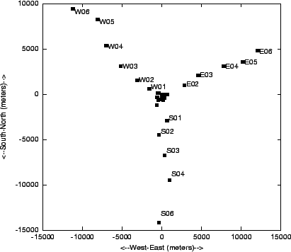
frequency interferometers like the GMRT (Fig. 1), there is a
serious dearth of phase calibrators since a significant fraction of
the VLA calibrators are resolved at GMRT resolutions. The limit on
the maximum baseline can however be relaxed if the structure of the
source is known. Rest of the document describes a method of getting
the source structure, starting from a point-source model and the
corresponding uv(range)-limit.
is the antenna based phase correction. These are
traditionally determined from observations of an unresolved
source. However at low frequencies many of the VLA calibrators show
extended emission. Hence, they are not usable as the phase-calibrater
in the usual scheme of calibration (see references 1 and 2). This
imposes a limit on the uvrange1 that can be used to compute the
antenna based complex gains. Consequently, not all antennas can be
calibrated using a resolved source. For the predominantly low
frequency interferometers like the GMRT (Fig. 1), there is a
serious dearth of phase calibrators since a significant fraction of
the VLA calibrators are resolved at GMRT resolutions. The limit on
the maximum baseline can however be relaxed if the structure of the
source is known. Rest of the document describes a method of getting
the source structure, starting from a point-source model and the
corresponding uv(range)-limit.
Figure:
The figure shows all the 30 antennas of the GMRT with 14 of
them clustered in the Central square and rest along the Western,
Southern and Eastern arms.
 |
Next: Bootstrapping for antenna gains
Up: Procedure for extending uv-limit
Previous: Procedure for extending uv-limit
Sanjay Bhatnagar
2003-10-17