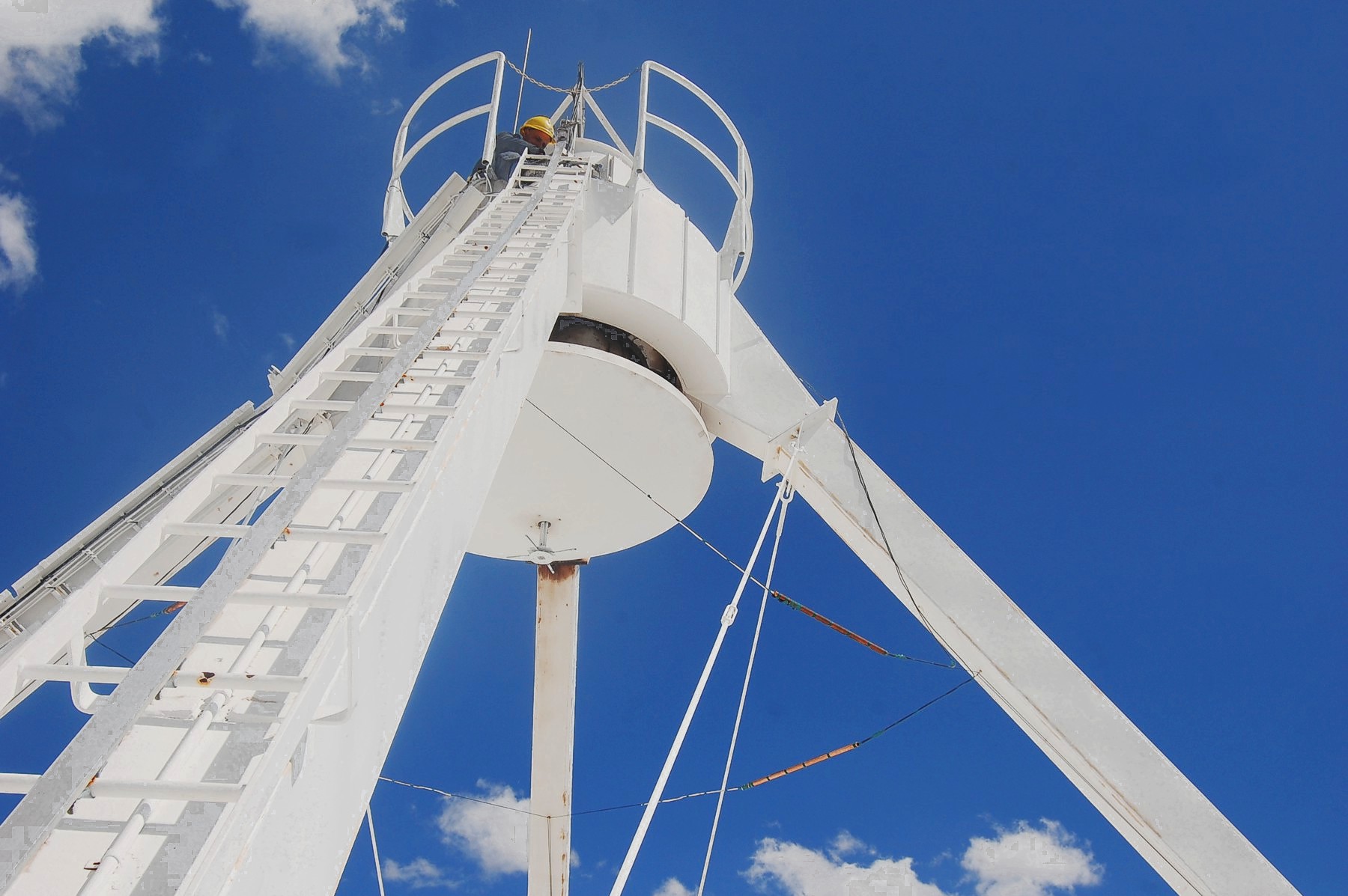
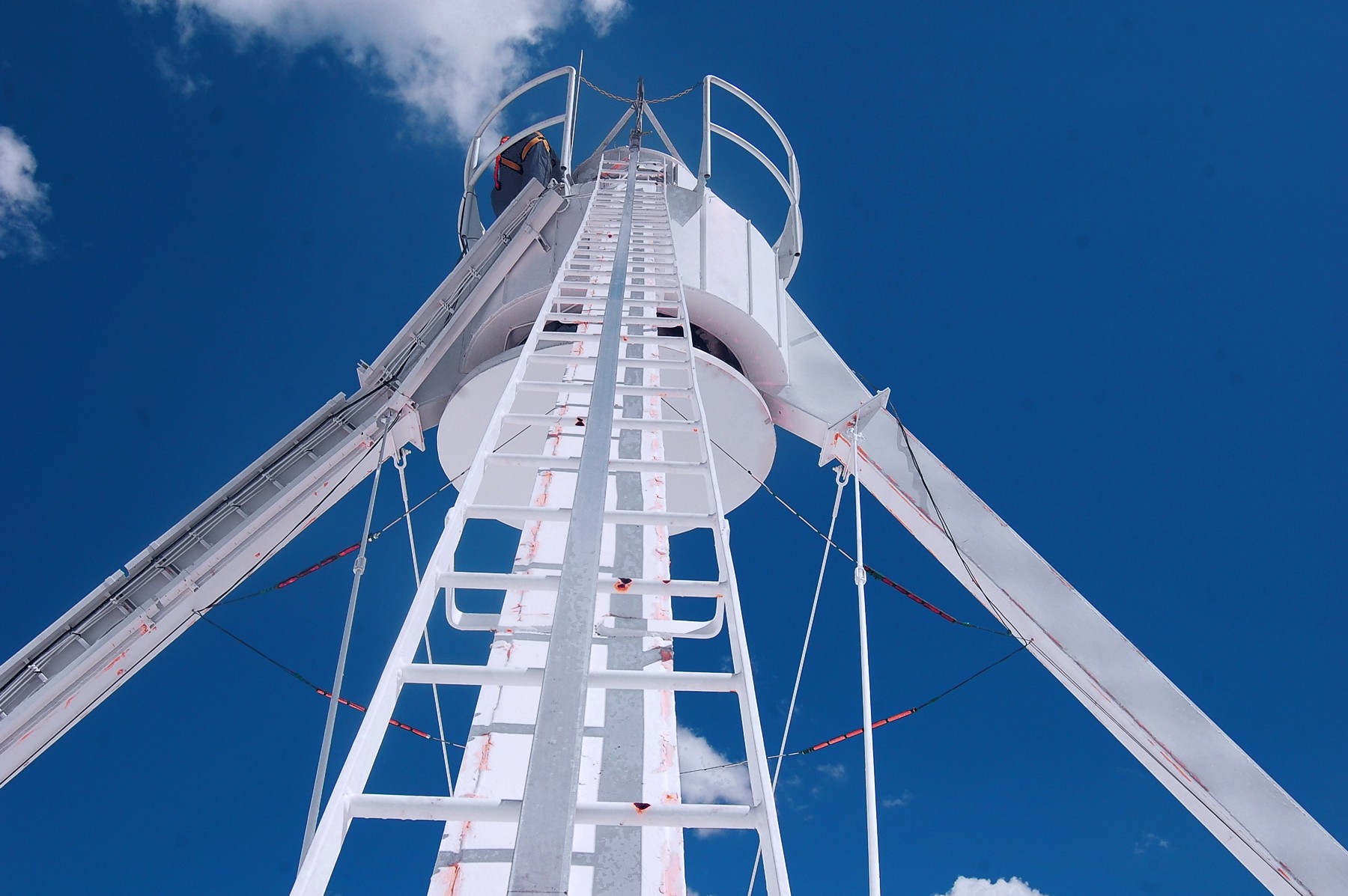
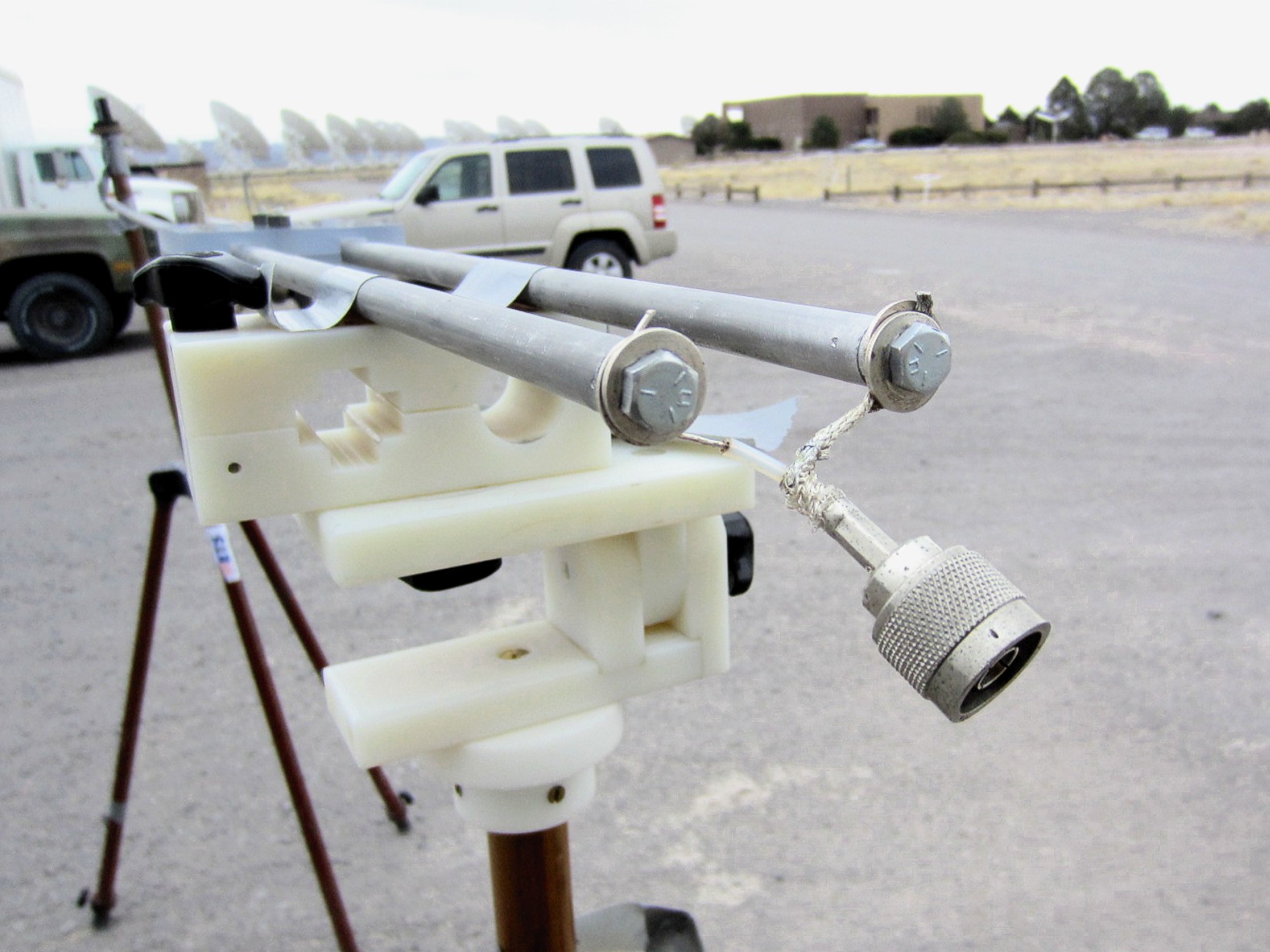
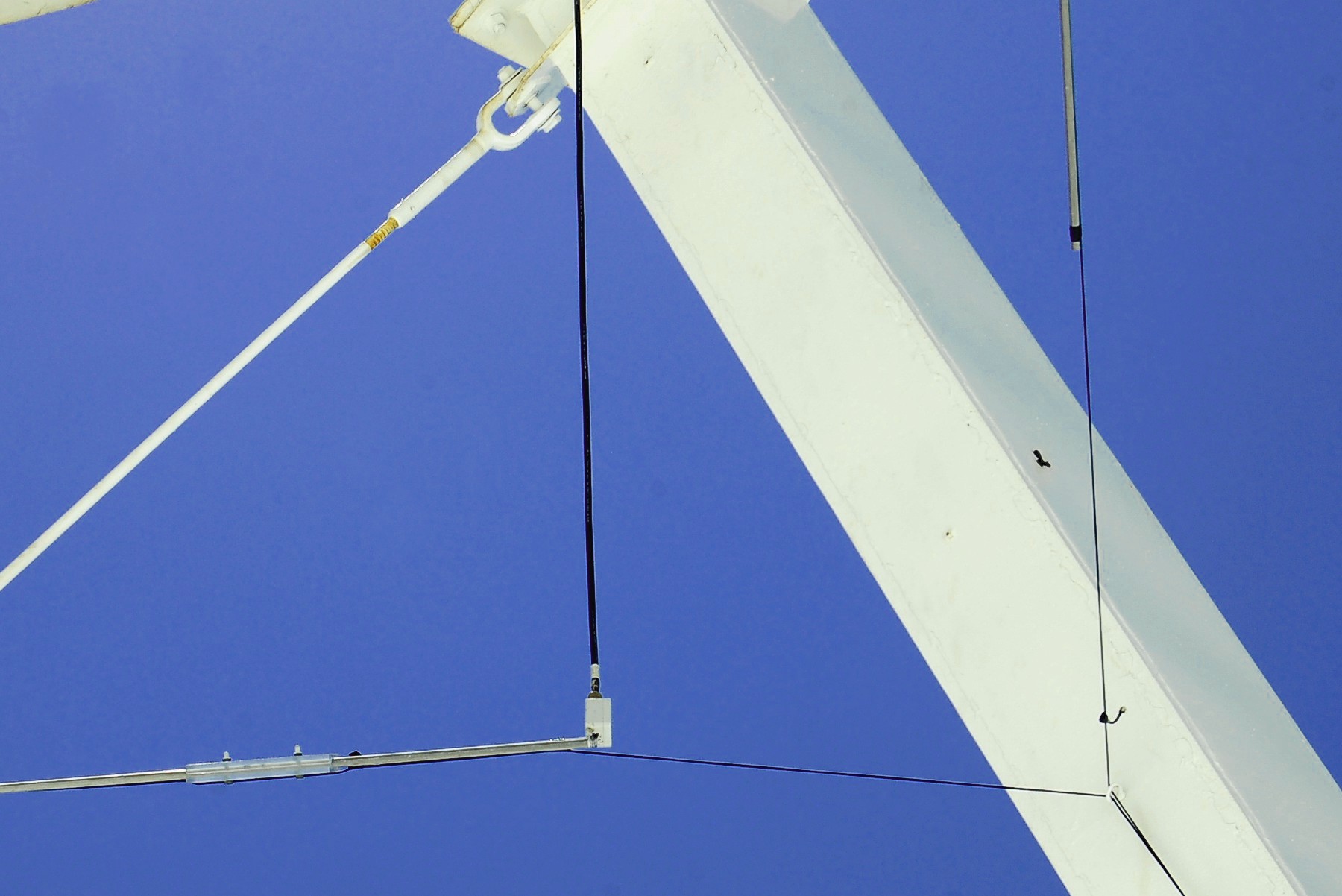
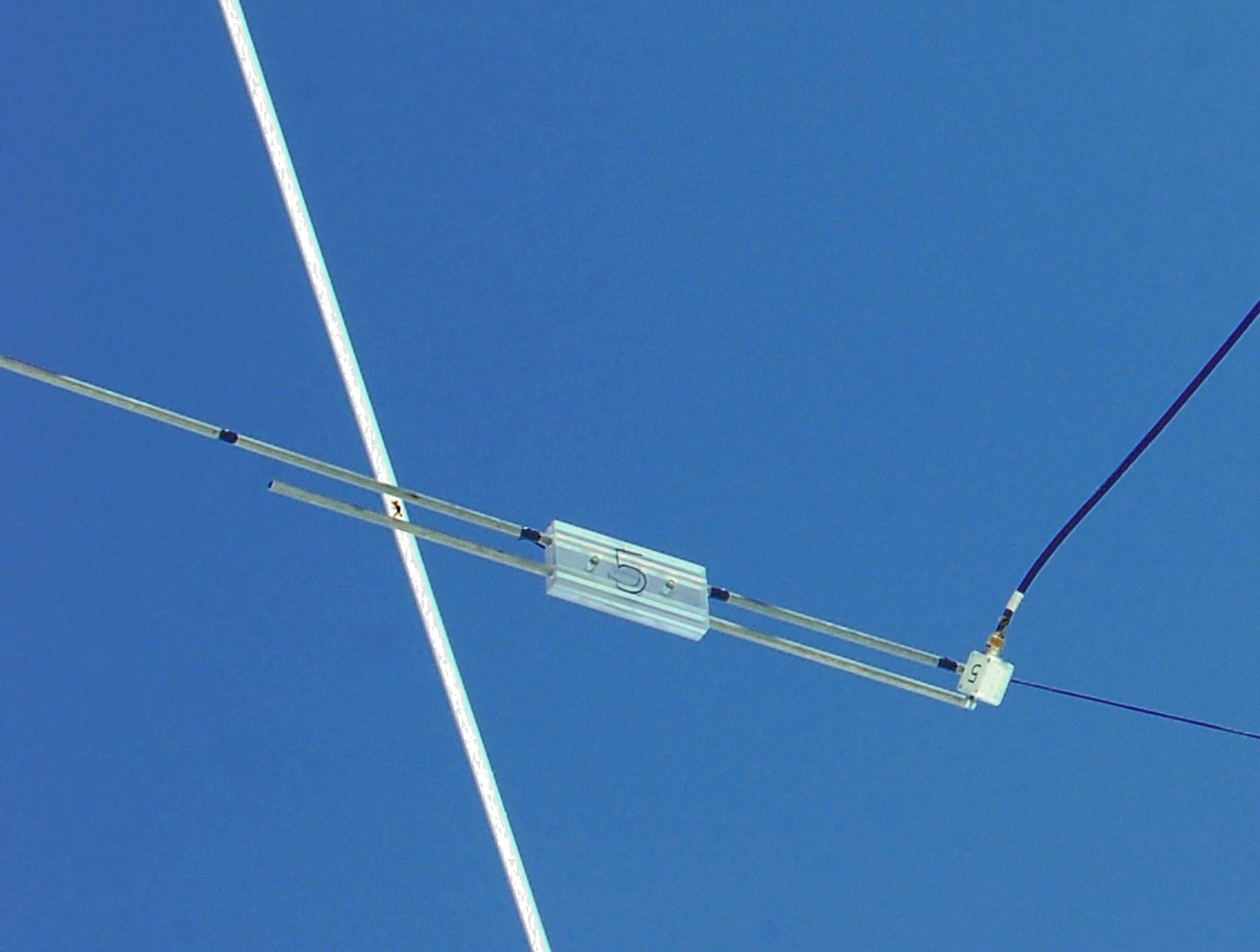
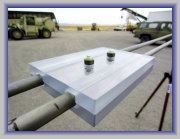
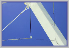
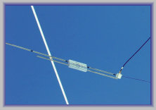
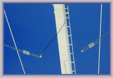
Views of the bazooka dipoles installed on VLA antenna 5
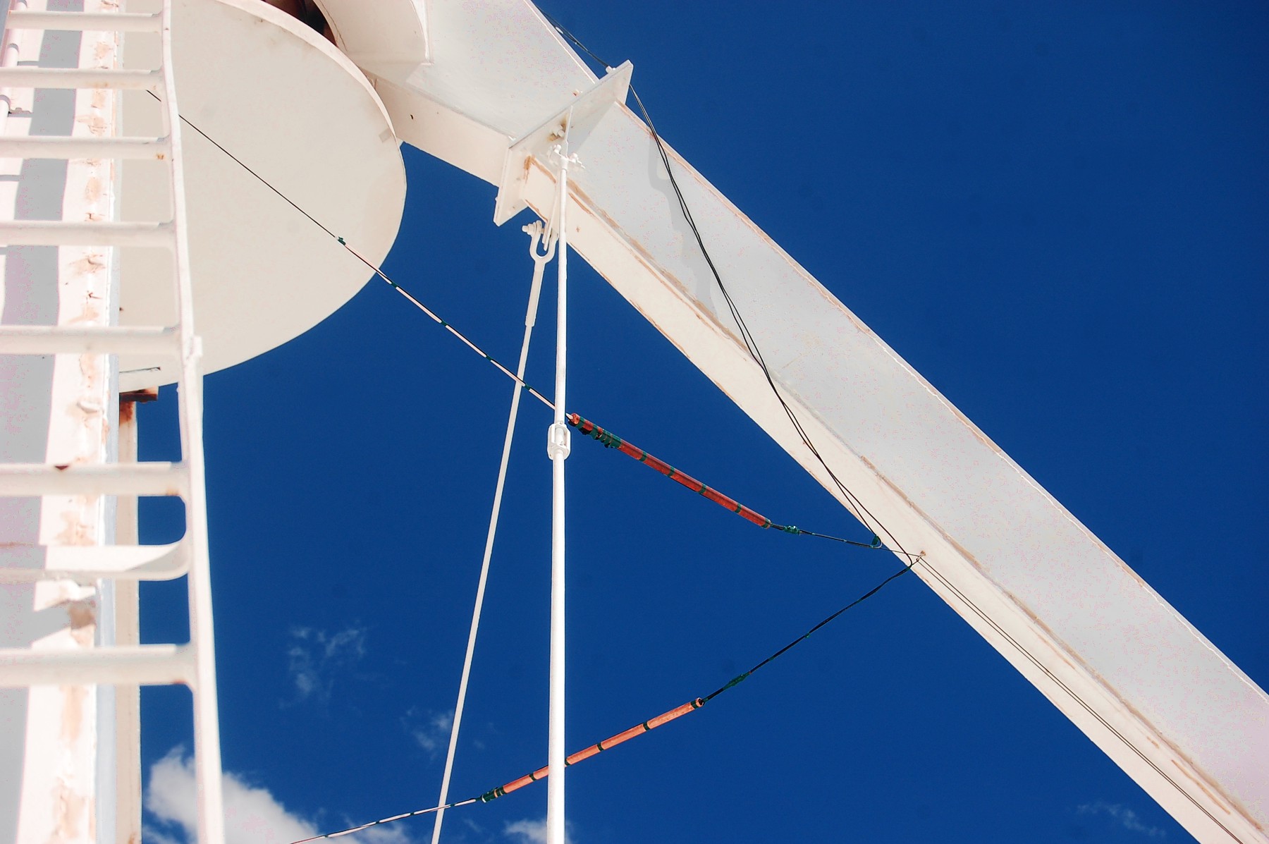
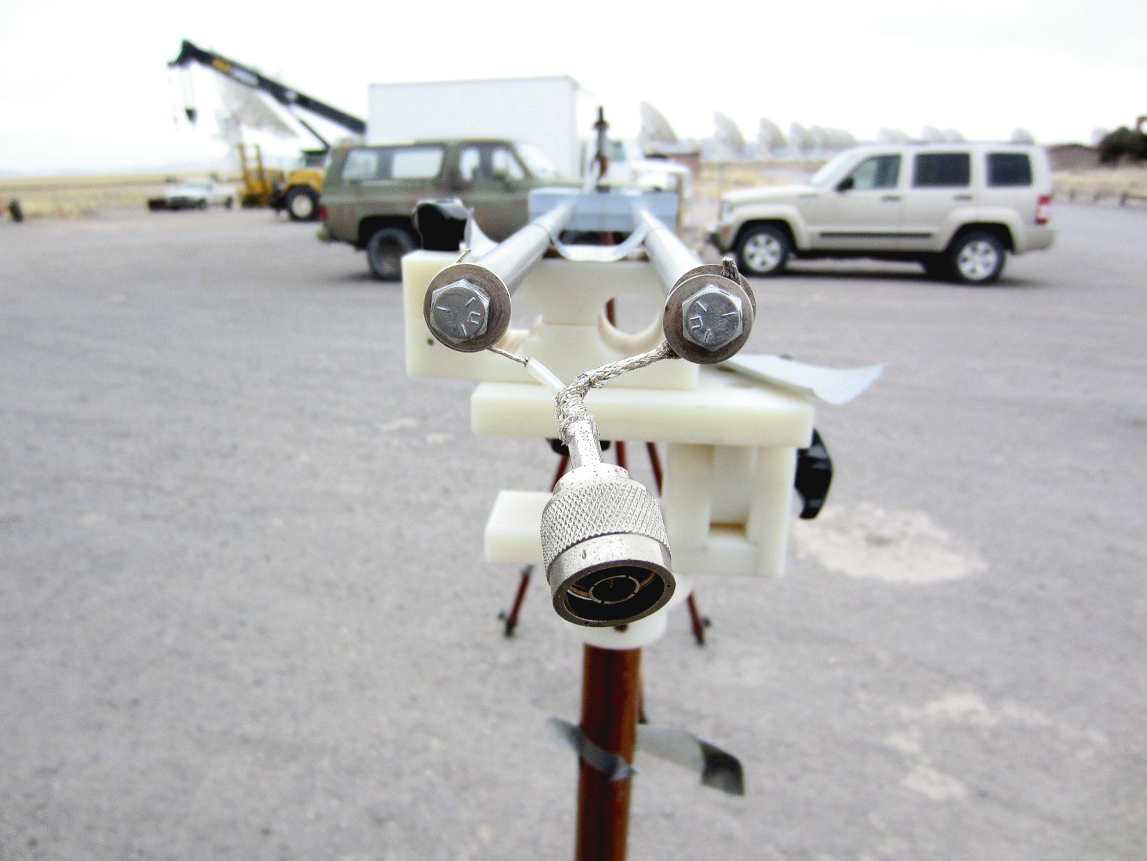
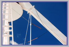
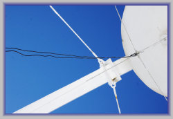
Close-up of two elements and feedlines goint to receiver in the apex
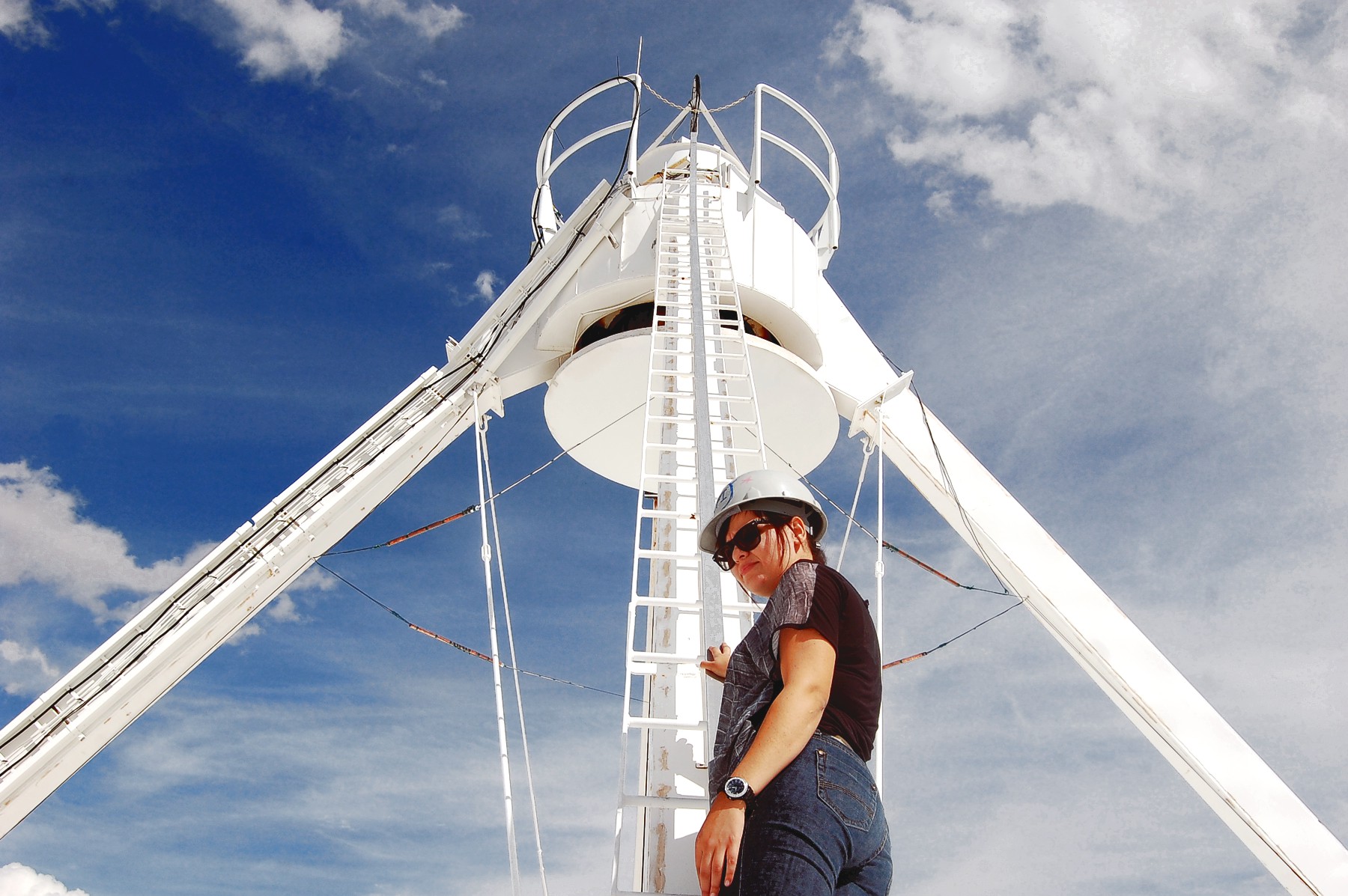
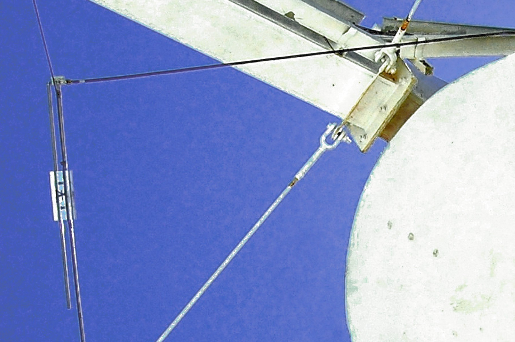
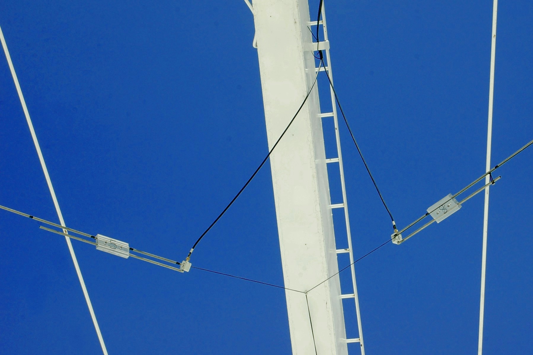
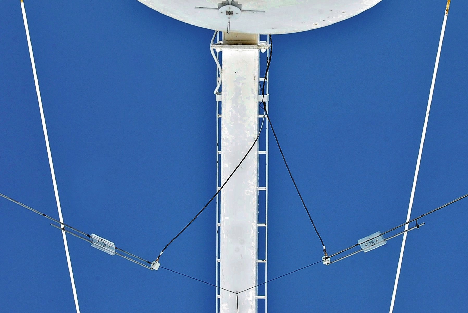
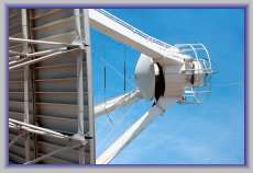
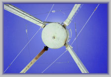
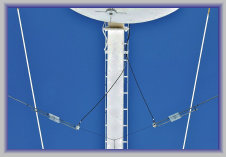
Bazookas on ant. 5 with the
dish tipped over
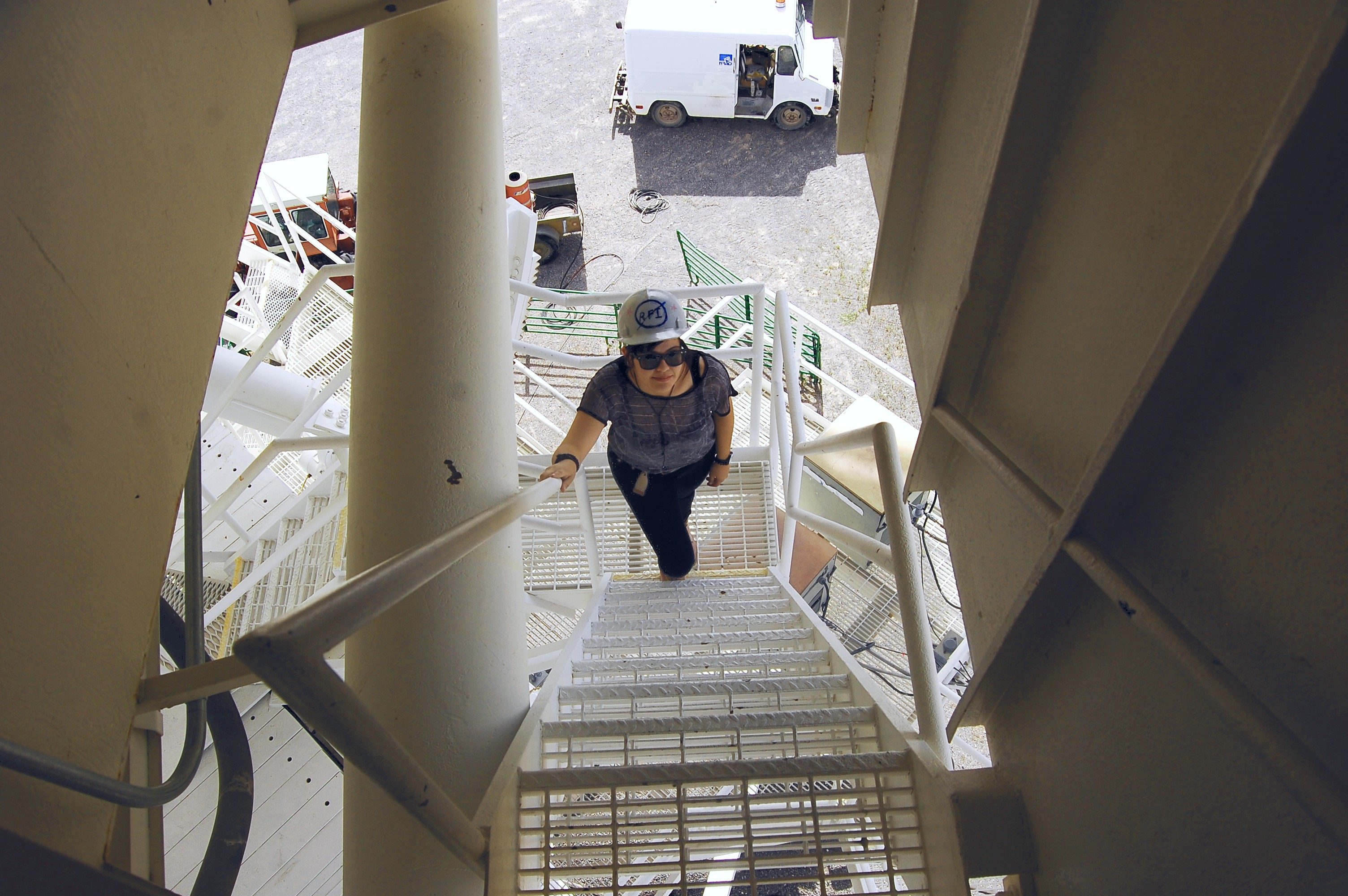
Construction, installation, and testing assisted by
EE student and Intern Diana L.


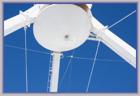
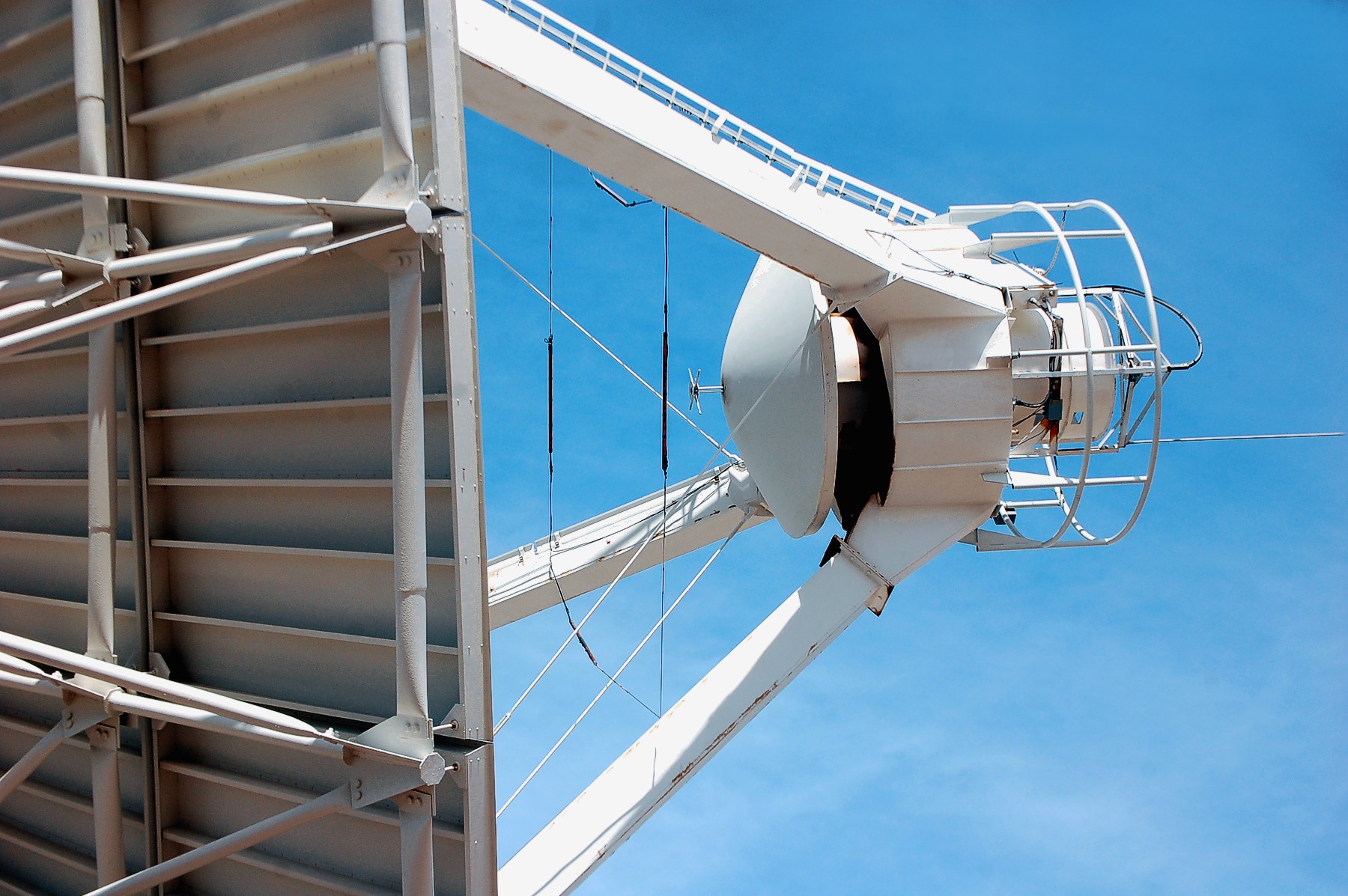
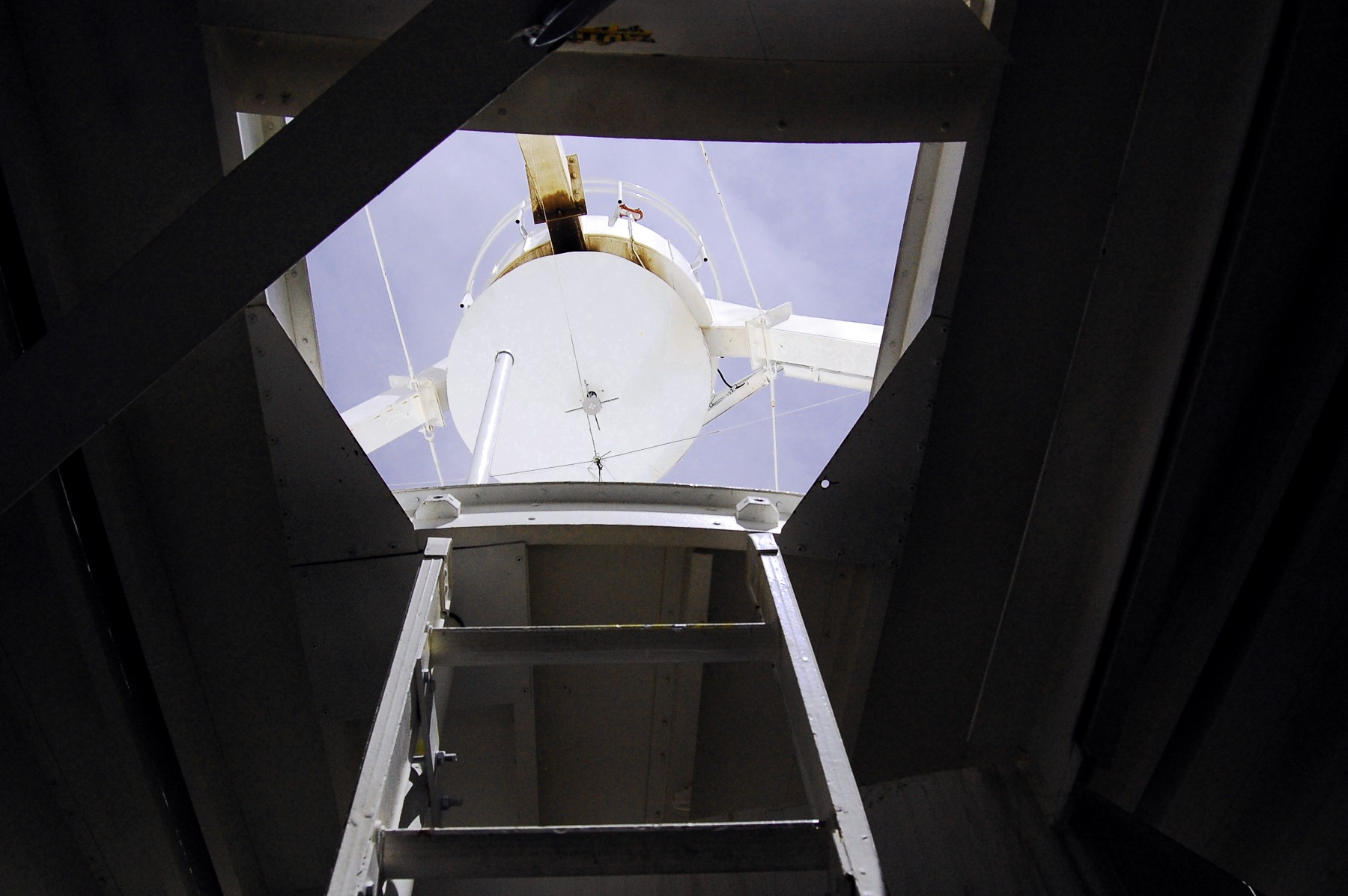
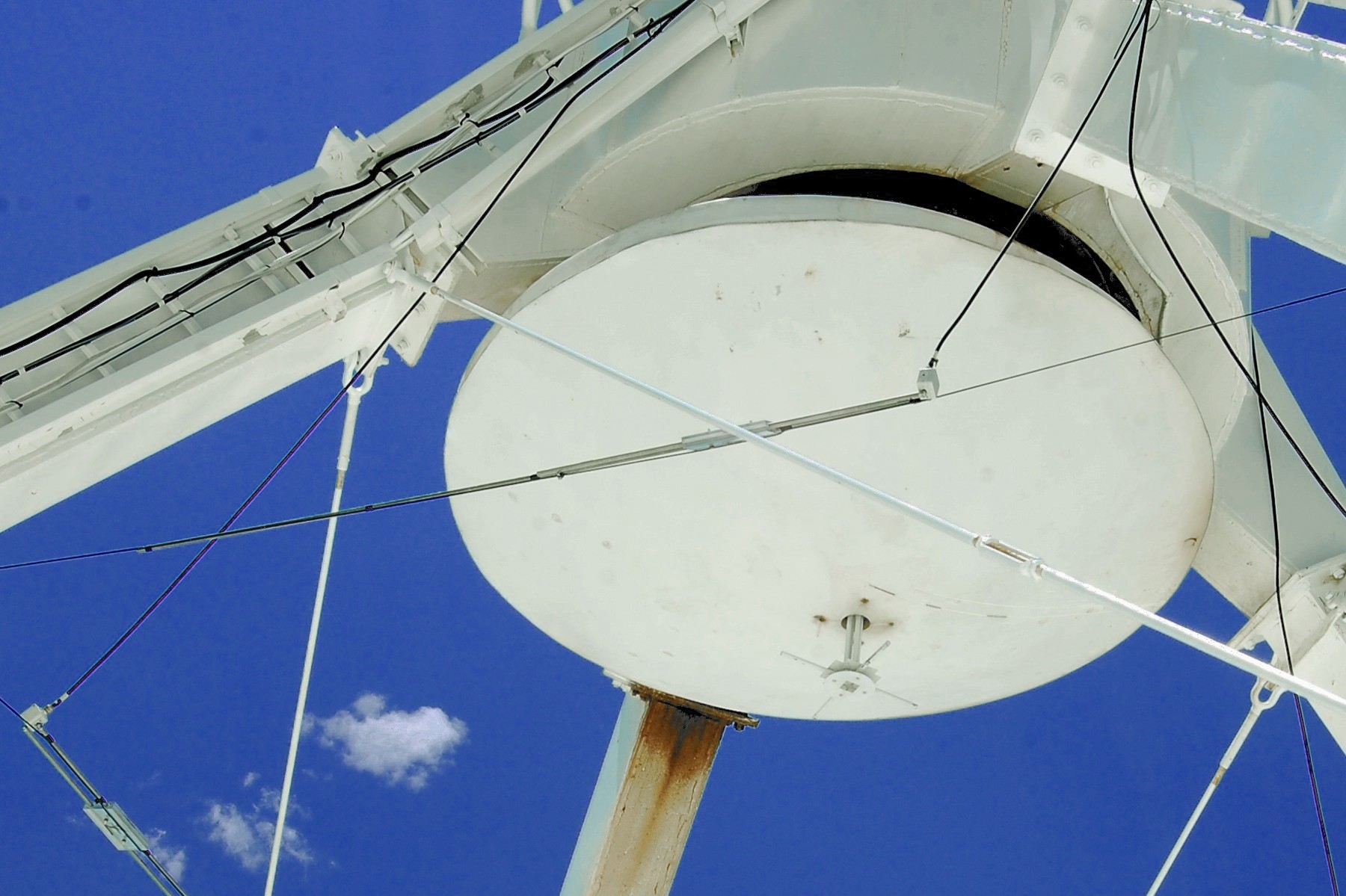
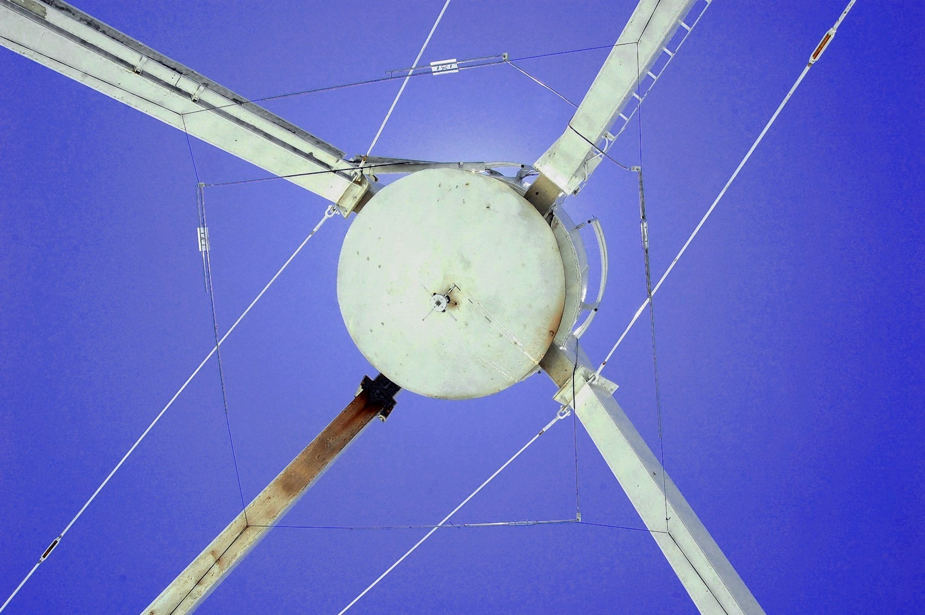
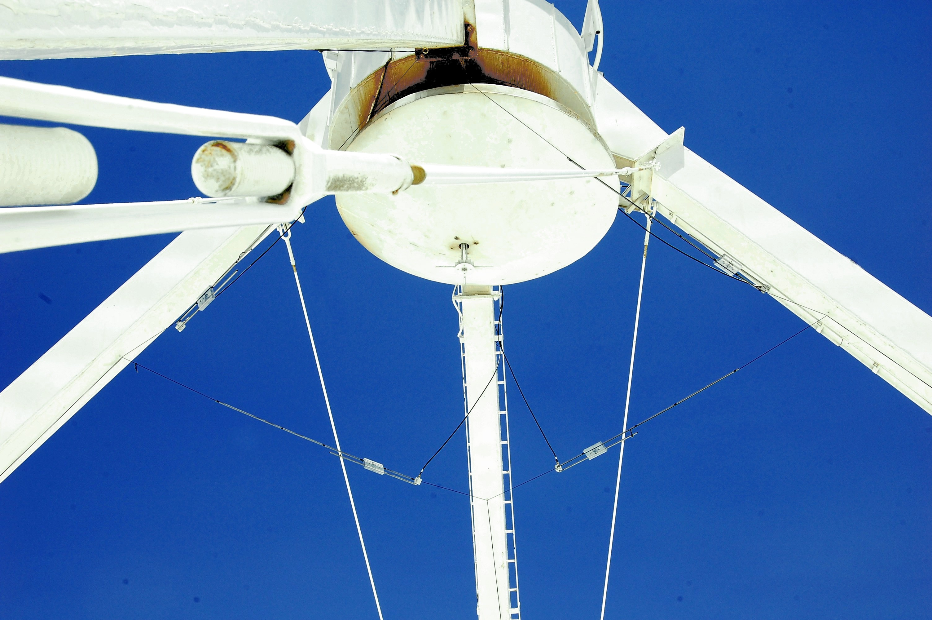
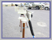
Erickson 74 MHz dipole raised on the VLA antenna
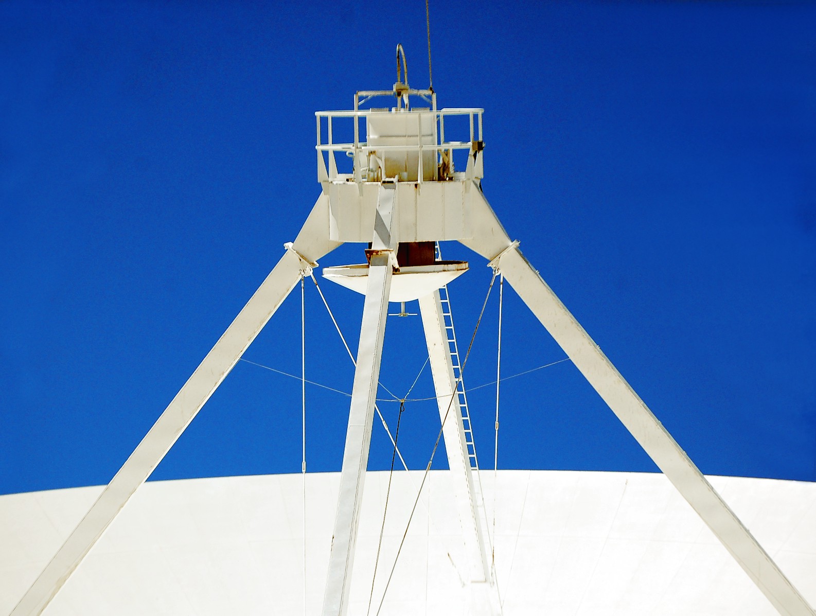
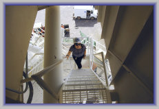
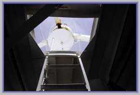
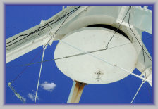
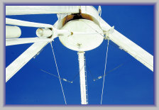
View of apex & dipole
through dish hatch
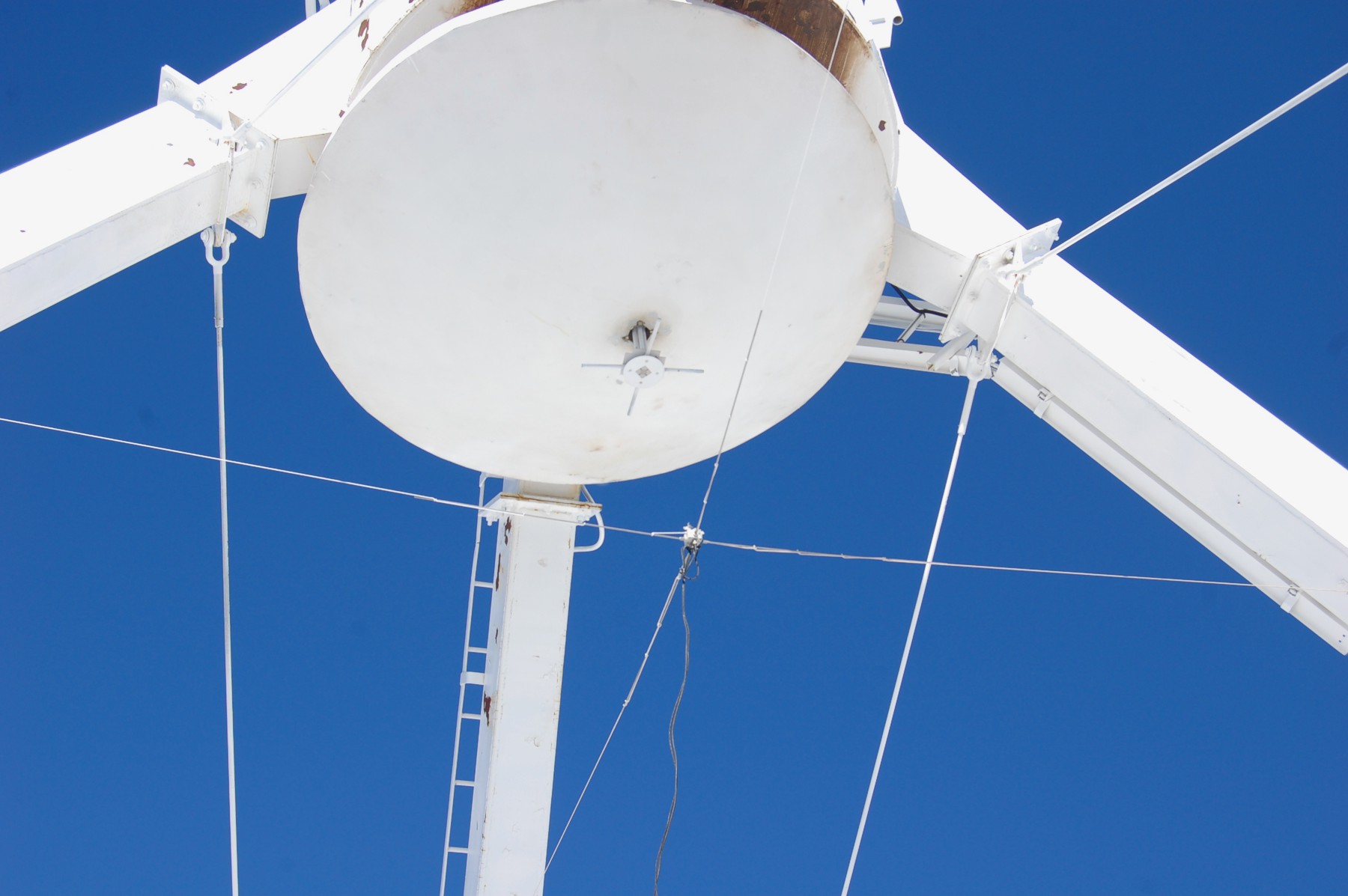
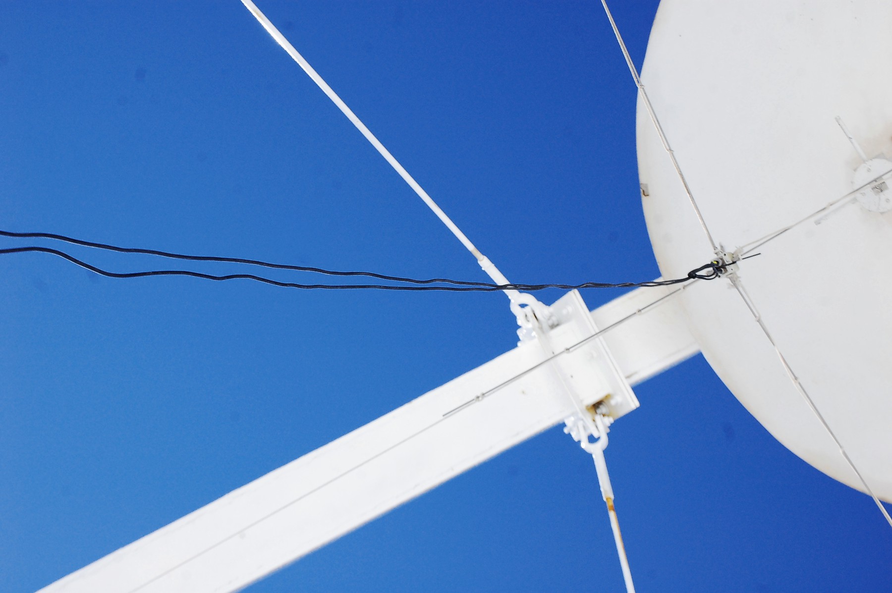
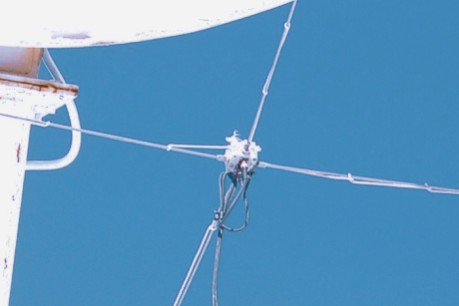
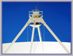
View of dipole under the subreflector
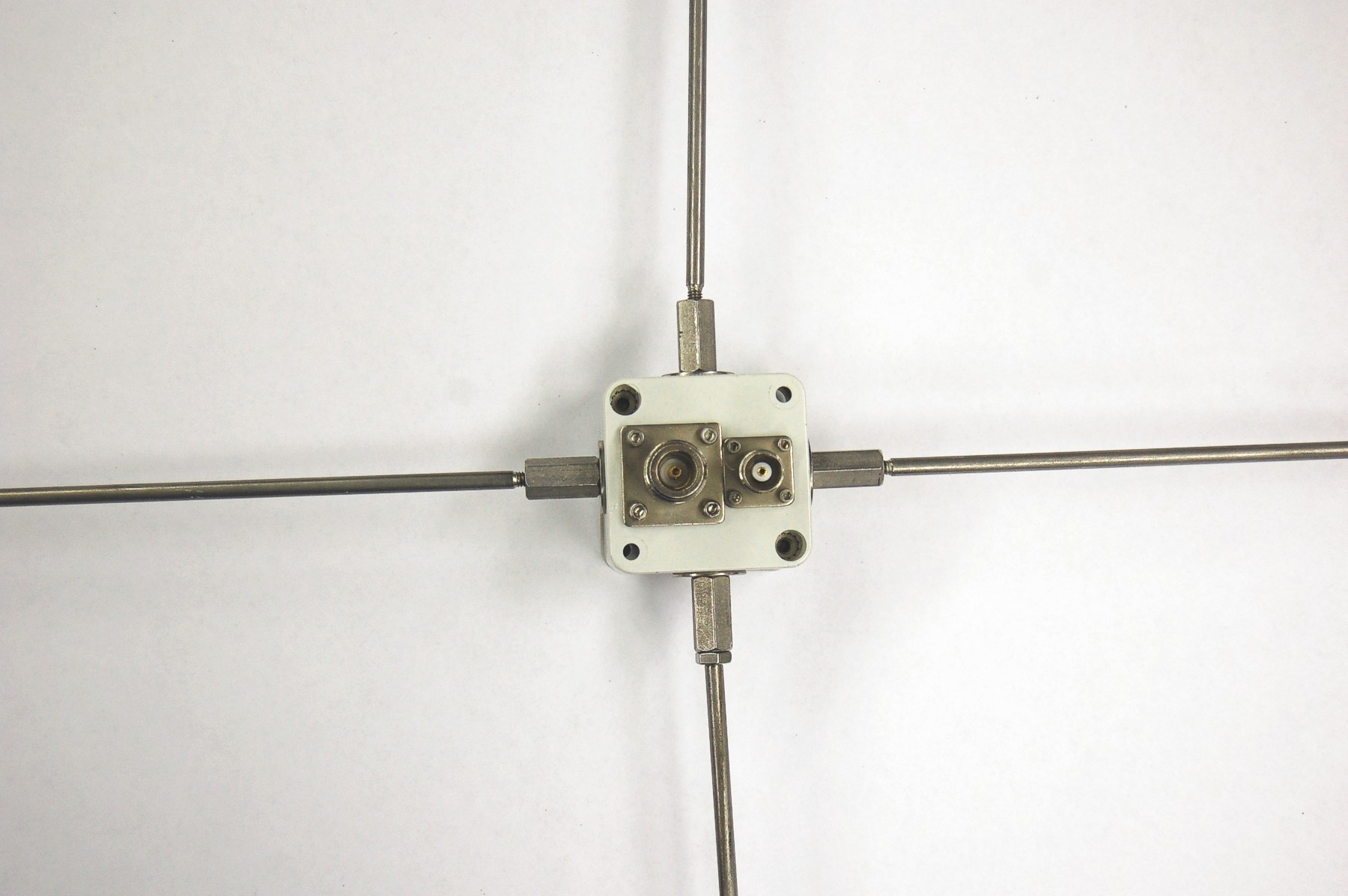
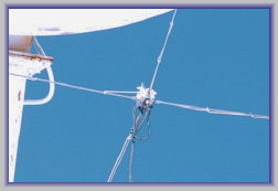
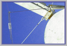
Closeup of the dipole balun box & feed lines


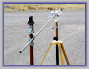
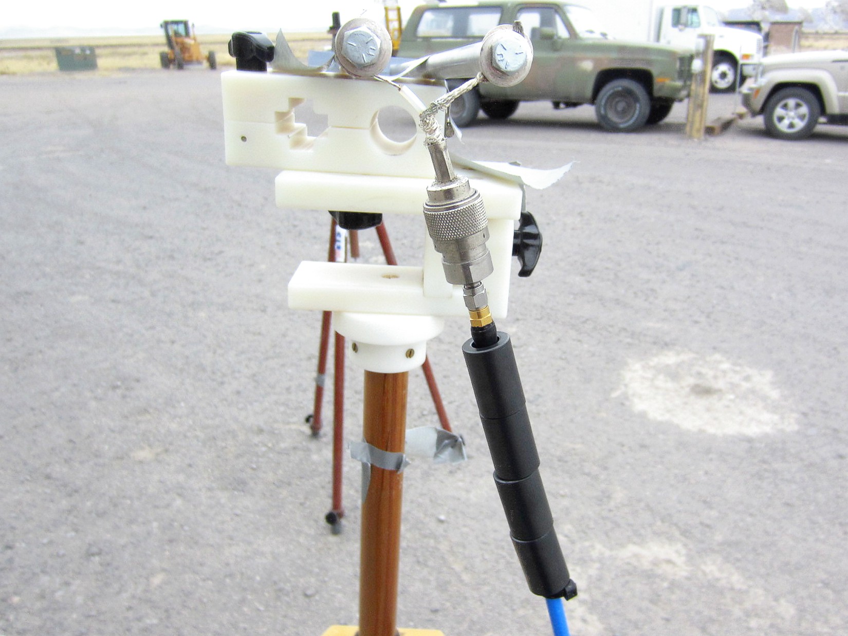
Dan M. and Sterling C. building and testing the MJP at the VLA site
GTX145934
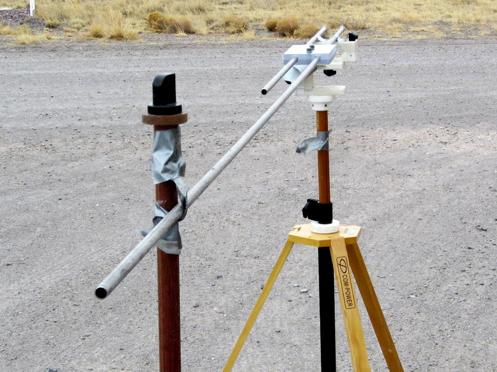
The Modified J-pole antenna installed on EA27
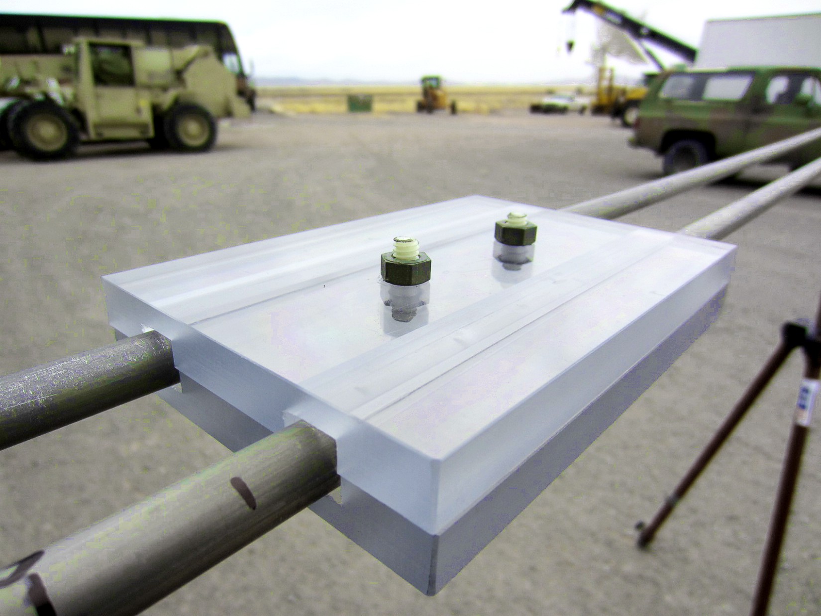
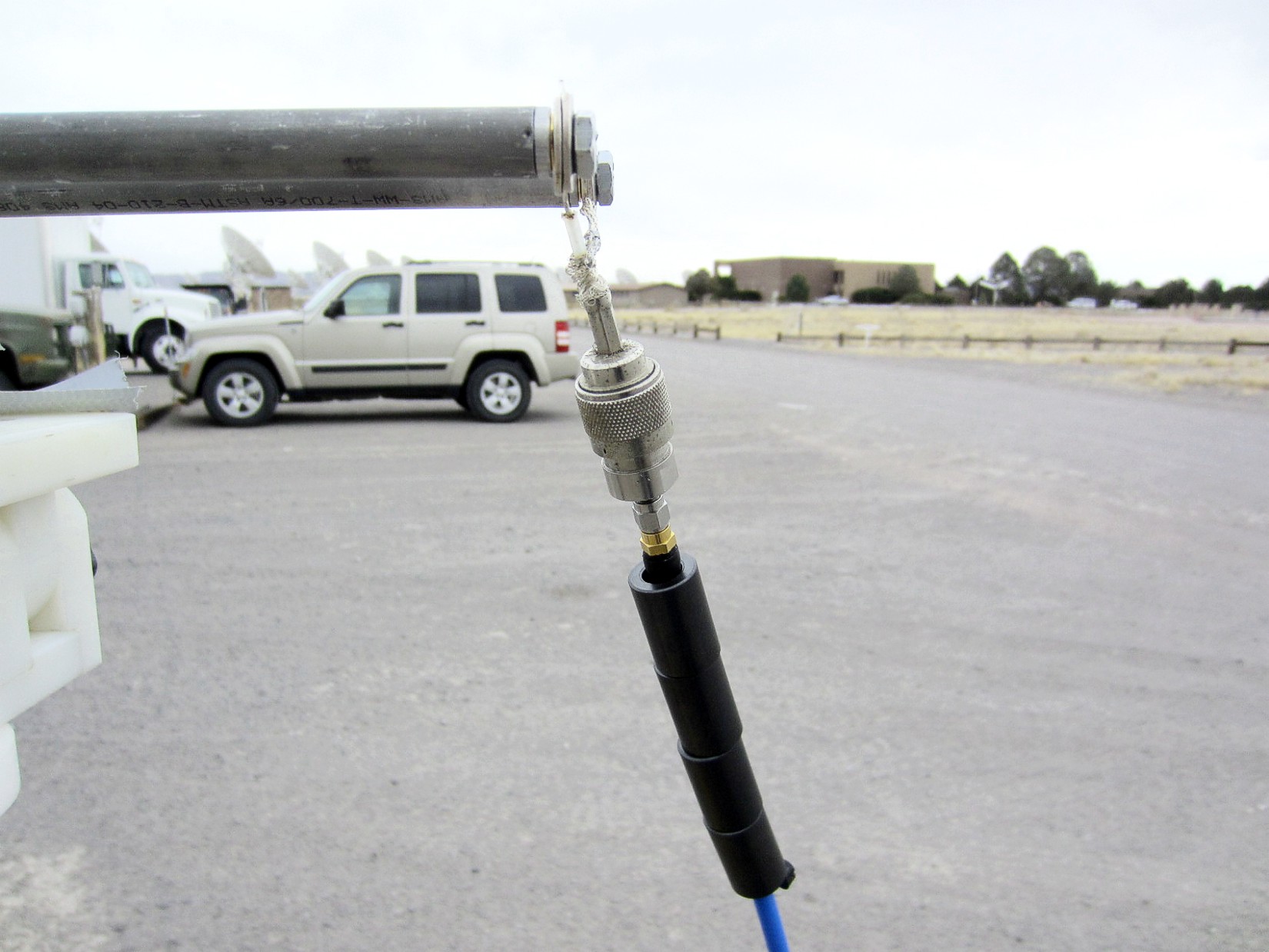
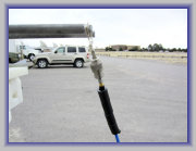
Close ups of J-pole elements, coax termination, and mounting ropes

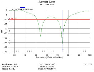
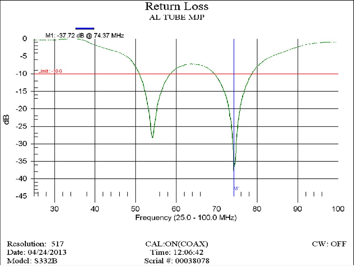
Aluminum Version MJP
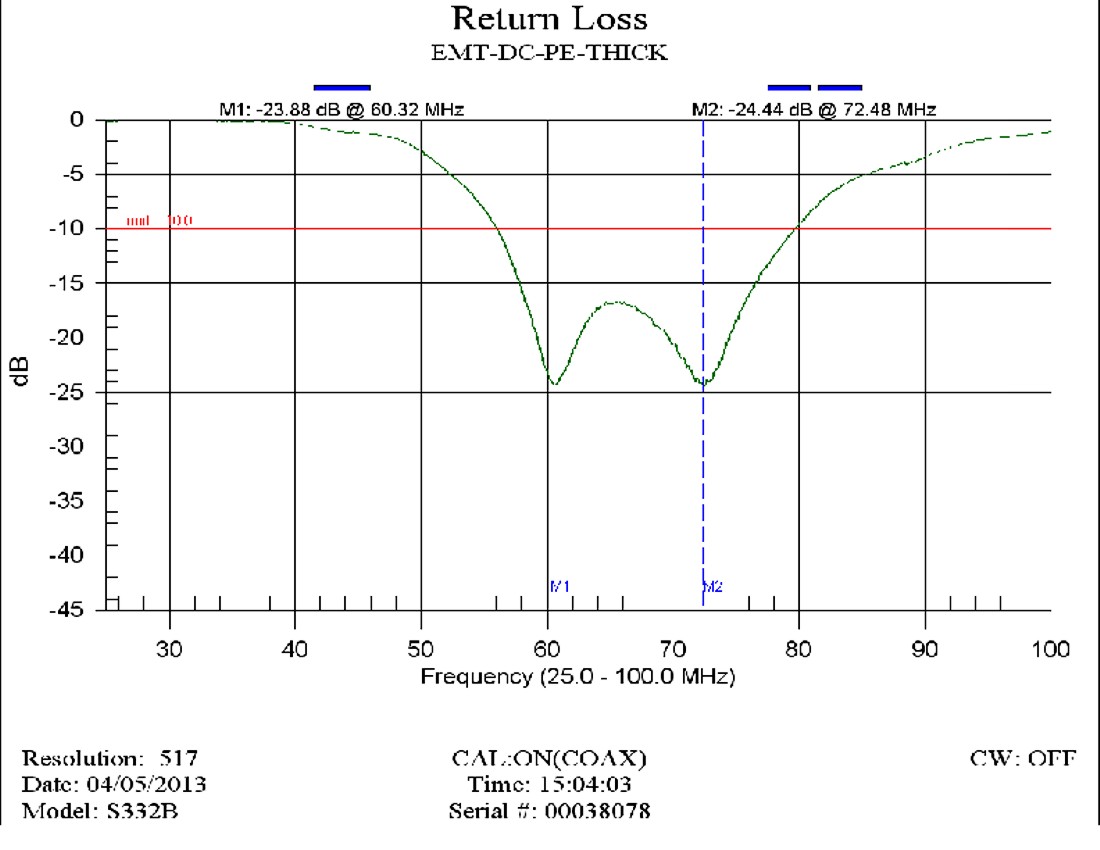
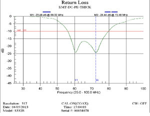
Galvanized Steel Version MJP
Reflected Power Sweeps
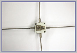
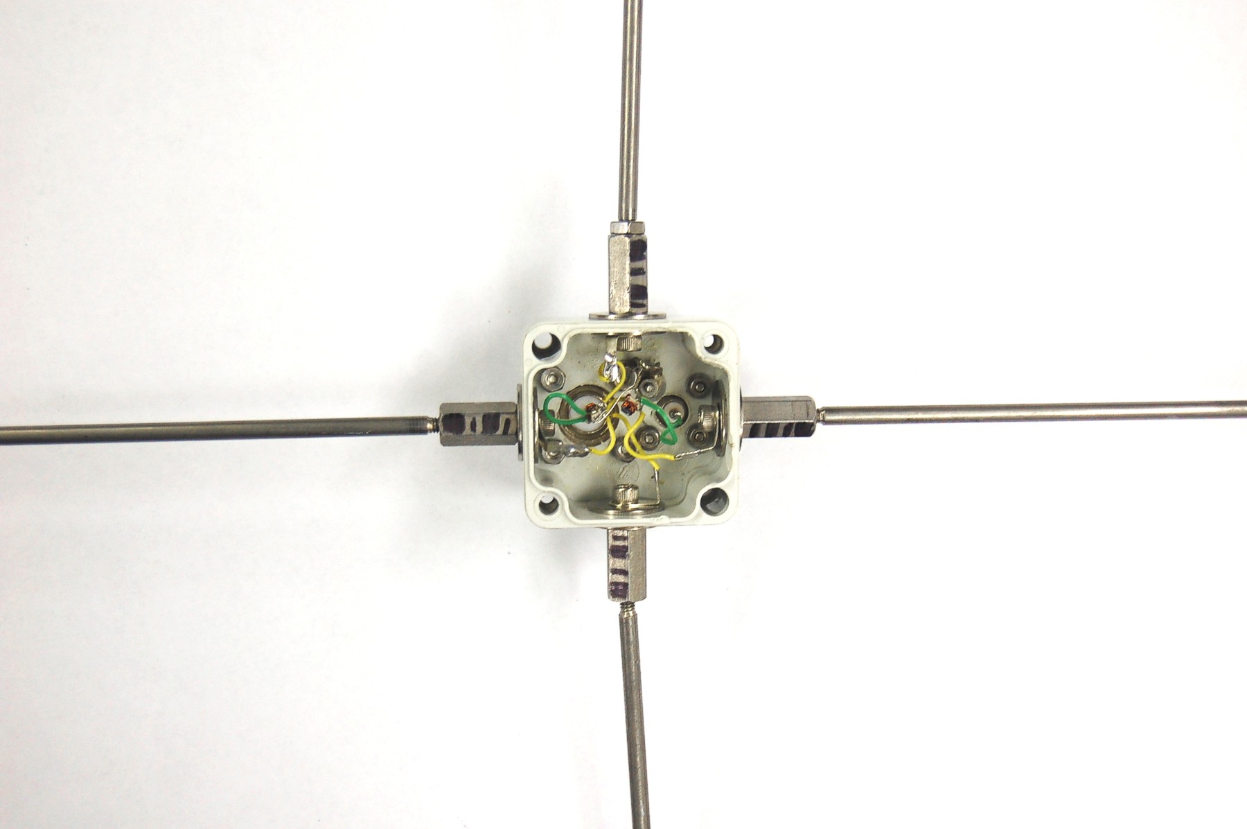
Balun box - connector side (faces dish surface). N-type is X (N-S)
polarization; TNC is Y (E-W) feed.
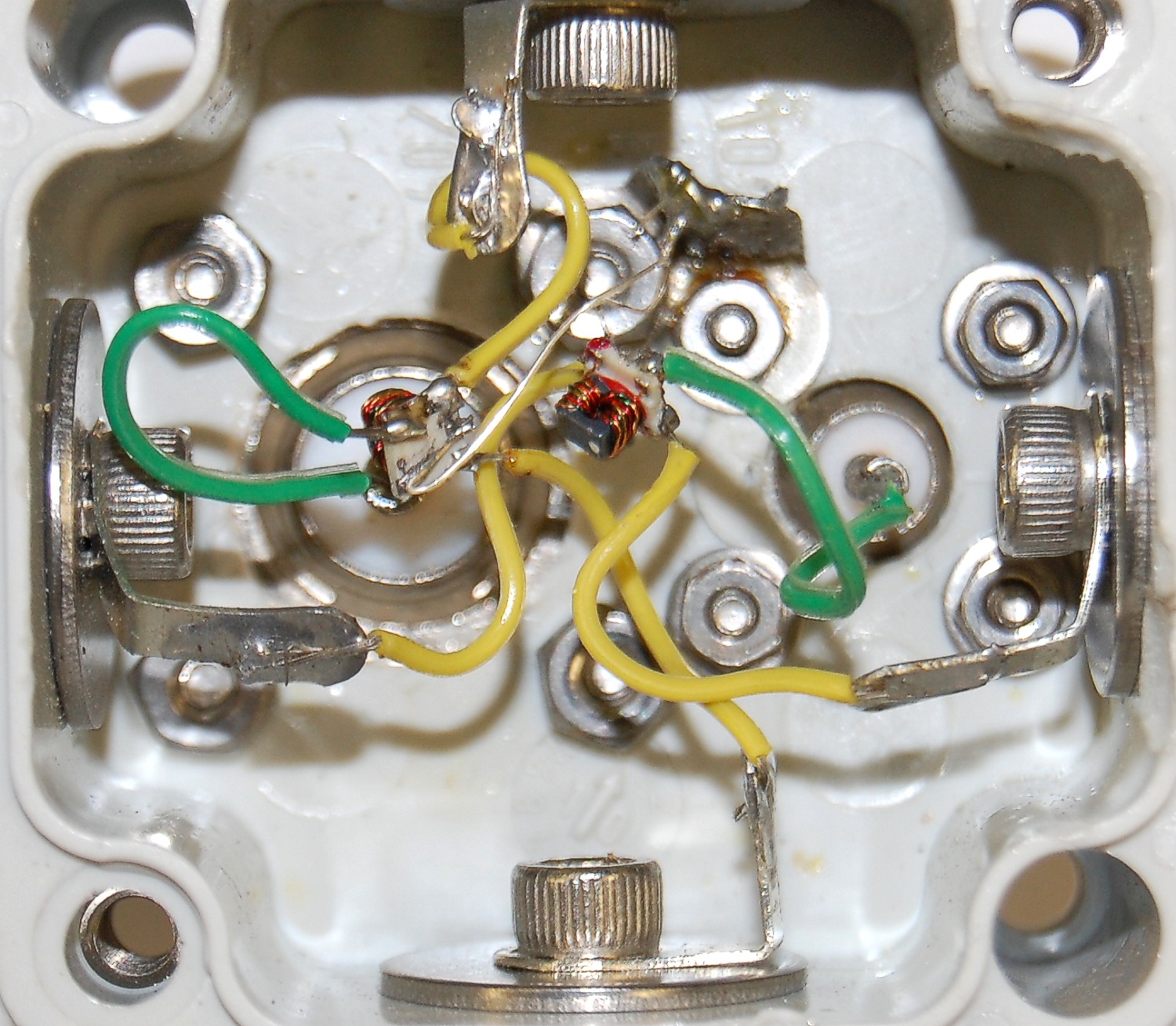
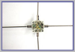
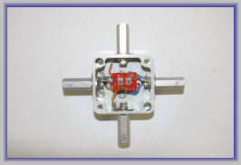
Balun box - top side (faces subreflector) with cover removed to show balun components
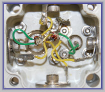
Detail of old balun box showing "dead bug" construction.
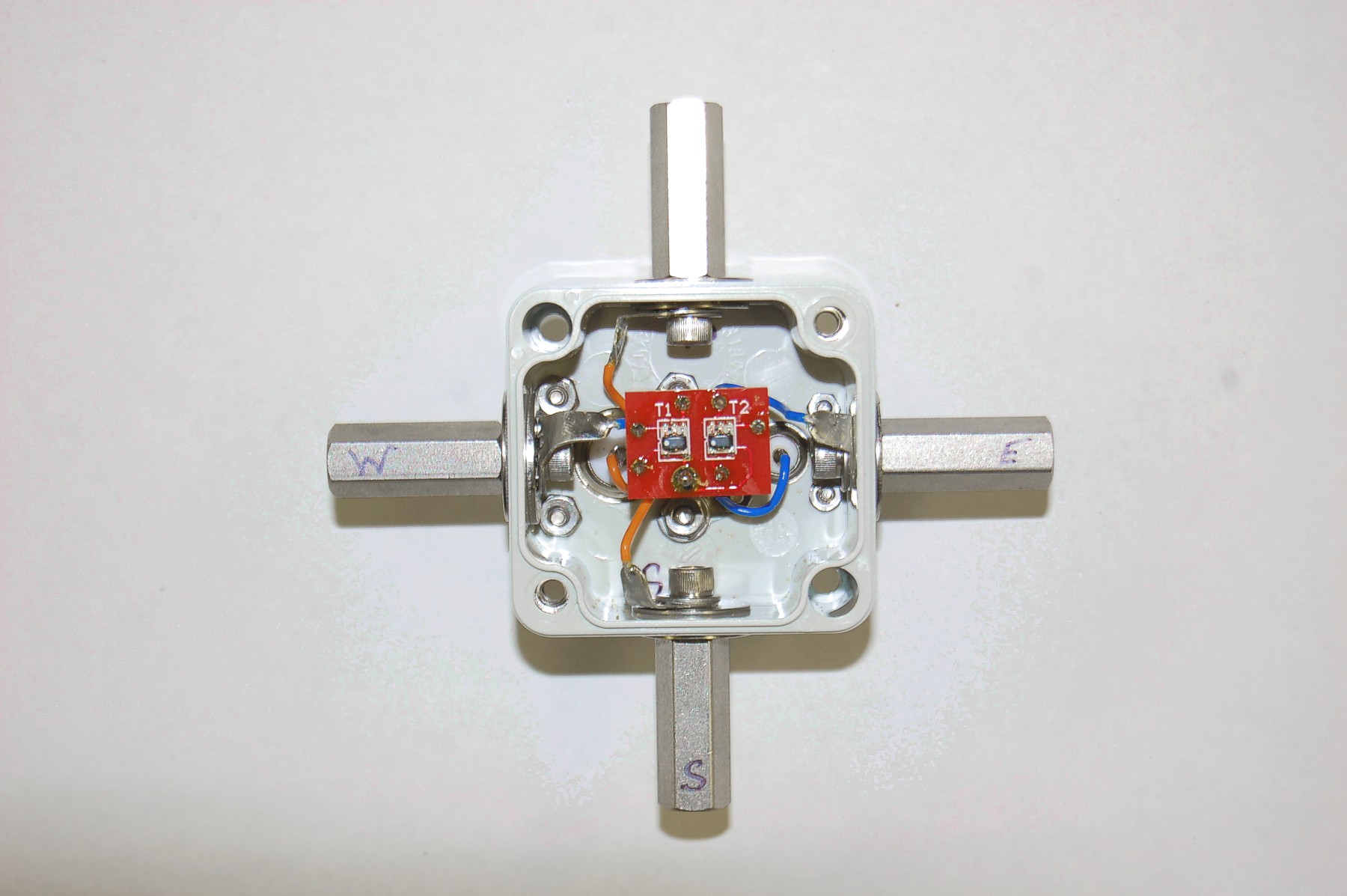
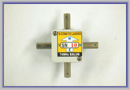
Balun box - top side - with new label to ensure proper orientation
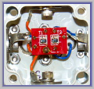
Balun box - top side - with cover removed to show new balun PCB
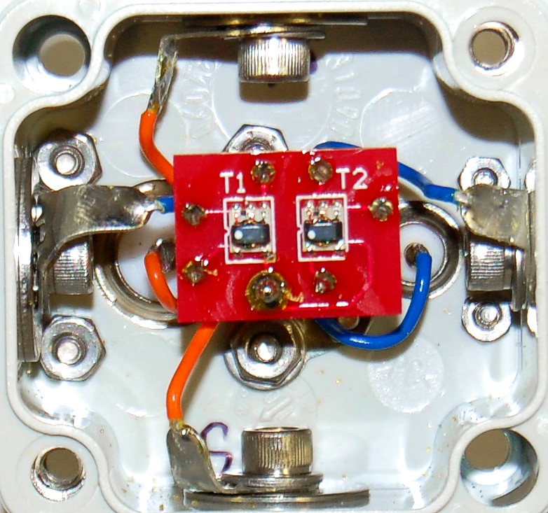
Detail of balun transformers mounted on PCB
What's on this page?
Click photos to enlarge to 300 dpi
Page 4
NRAO/NRL Low Band Receivers

Gallery Page: