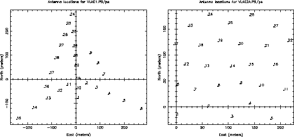
Figure 2.4: Examples of possible E configurations: the E1 (left)
requires only 9 new
antenna stations and two new rail spurs; the E2 (right)
requires 27 new stations and five or six new spurs.
When the VLA was designed, little emphasis was given to achieving good sensitivity to low surface brightness features, to imaging of fields of view wider than its primary beam, or imaging with lower angular resolution than that provided by the D configuration. Mosaicing had not been developed and it was believed that, in any case, such issues were better addressed by large single dishes. It is now recognized that compact arrays with total power capabilities fill a gap between the imaging capabilities of conventional interferometer arrays and those of single dishes.
An ultra-compact E configuration with maximum baseline lengths of a few hundred meters would allow efficient high-fidelity imaging of extended, low-surface brightness emission on angular scales larger than the primary beam. Support of this configuration will require new antenna stations and rail access to them.
The E1 option is to move the outer three antennas from each arm of the D configuration to the inner part of the configuration. This would require nine new stations and two new rail spurs (Figure 2.4) and provide a maximum baseline of 500 m. Simulations show that it would reach a given surface brightness sensitivity twice as fast as the optimally tapered D configuration.
The E2 option would use 27 new stations and five or six new rail spurs to provide essentially Nyquist-sampled coverage and a small grating response. Simulations of the configuration in Figure 2.4 show that it will reach a given surface brightness sensitivity five to ten times faster than the D configuration.
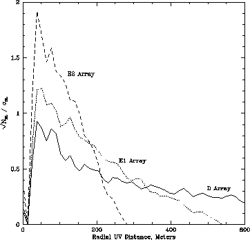
Figure 2.5: Relative sensitivities of the D, E1 and E2 configurations.
Fig. 2.5 compares the relative sensitivities of the
D, E1, and E2 configurations (parameterized as the filling factor of
antennas in the area covered by the array). The E2 configuration is
preferable, but is estimated to cost about four times the E1.
Shadowing is of little concern for either possibility for hour angles
![]() HA
HA ![]() and source declinations
and source declinations ![]() . Long tracks are not
needed for good coverage; snapshots at several hour angles will
suffice for many programs. For low declination sources, a hybrid or
``E-south'' array configuration may be needed.
. Long tracks are not
needed for good coverage; snapshots at several hour angles will
suffice for many programs. For low declination sources, a hybrid or
``E-south'' array configuration may be needed.
In principle, much of the same capability for imaging low-surface-brightness emission could be obtained by using array feeds on a large single dish, the GBT. In practice, the E configuration would guarantee this capability for all VLA observing frequencies and simplify mingling of the data with those from other configurations.
An alternative to constructing new rail spurs and VLA antenna stations might be to develop the E configuration as a test-bed for prototype antennas for (some versions of) the proposed Square Kilometer Array.