 { I, II, III, IV }
(A
{ I, II, III, IV }
(A  B)
B)
| ALMA Correlator Specifications and Science Requirements Revisited | |
This memo presents a summary of the current planned capabilities of the ALMA correlator system, including the LTA/adder tree and FFT computers. In particular, the data streams are traced through the system, and data rates needed to handle the various modes are computed. This document is intended for the technical user, working group member, and advisory committees, and as such gets into a fair bit of detail on how things are done in the designs. The first one-quarter (likely one ``array'') of the ALMA correlator is scheduled for delivery in 2004, and it is critical that this be able to do good sciencific work with approximately half of the projected total of 64 antennas. Although the current design has each array of the correlator most naturally assigned to a pair of polarizations from a single baseband pair for 64 antennas, the most desirable thing would be to be able to trade antennas for bands, and thus be able to correlate all 4 baseband pairs for 32 antennas. The system design needed to ensure that we can get all of the necessary results out of the correlator in the minimum accumulation time of 16 ms is also outlined, with the upshot that the current design is about a factor of two off, and either an increase in bus speed or number of output data streams is necessary to clear the entire correlator in the highest bandwidth (least data intensive) cross-product mode. At the end of this memo, a number of comments and open questions are presented for consideration by the various working and advisory groups.
The current baseline correlator and LTA design can be found at
and we will refer to this diagram (included as Figure 1) in this memo. We will also refer to the design given in the preliminary memo on the LTA design (dated 8/27/99). The purpose of this memo is to inform the MAC/SAC and Imaging & Calibration teams about the features of the current design, how this design will impact the science goals, and what is required of the data analysis subsystem. This memo arose from discussions within the Imaging & Calibration group, and with Barry Clark, Brian Glendenning, and Chuck Broadwell. Jim Pisano and Ray Escoffier provided critical help in working through the design parameters. The discussion will be technical at times in order to give a clear picture of what the hardware is doing at a given time.
In general, the capabilities of the proposed ALMA correlator design are the same as those presented in Rupen & Escoffier (Memo 194). Furthermore, the scientific requirements are still those most recently presented in the white paper by Rupen, Shepherd & Wright (1998).
Each receiver in the antenna outputs two sidebands (the receivers are sideband-separating) and two polarizations for 4 independently tunable LO settings each of which give a 2 GHz IF (presumably at baseband) over the total RF bandwidth of at least 16 GHz, for a total of 16 output signals, which are then digitized. There are 8 4 GHz digitizers in the ``AT ANTENNA'' block. The sampling rate of 4 GHz allows a maximum bandwidth of 2 GHz per channel. The inputs to these samplers are fully configurable, and normally will probably be set to each of either the two sidebands USB and LSB, or two polarizations E and H for the 4 baseband pairs; note that depending on the particular receiver for the band, the waveguide polarizations E and H might correspond to circular polarizations R and L on the sky, or two orthogonal linear polarizations. In other words, for full polarization, the pairs are E and H from one of the sidebands of the baseband pair, or for single polarization E or H from both sidebands of the pair.
At the antenna, the digital signal is filtered, the bulk (and possibly fine) delays are applied, and the samples are sent into 32 × 125 MHz (the fundamental clock frequency of the system is 125 MHz) streams. At the FIR filter blocks, there is the option to decimate (actually to progressively halve, or ``duomate''?) the 32 streams, and thus free up later processing for more lags to increase spectral resolution at the cost of total bandwidth (you are effectively dropping the sampling frequency). The minimum effective sampling frequency thus available is 125 MHz, which gives a bandwidth of 62.5 MHz in highest resolution mode. At the end, the 4 streams of 2 ``polarizations'' each are multiplexed into the optical transmission fiber to be sent down to the correlator station.
At the "CORRELATOR STATION ELECTRONICS" block the signal from the antennas gets de-MUXed back into 4 streams of 2 each which go to the 4 Station Cards, each of which goes to one "array" of the correlator. The correlator group thinks of the two streams into a station card as being a "baseband pair", which again in non-polarization mode will be the two sidebands USB and LSB, either E or H polarization, or the E and H polarizations from one sideband USB or LSB in full or dual polarization mode. For the purposes downstream, we will refer to these as ``bands'' A and B from a given antenna, and the pair as (A,B).
At this point the choice of what to feed the 4 correlator arrays, which we will designate as {I, II, III, IV}, is made. Each array has 4 sets of 2 polarization ``inputs'' which are each 64 antennas wide times 32 planes deep. Normally, these would correspond directly to the basebands {1-4} with polarization pairs (A,B). However, the arrays of the correlator can in theory be ``ganged'' together to correlate extra lags for a given baseband pair in order to increase the spectral resolution. For example, while for full polarization and maximum bandwidth one would normally use the mapping
{ I, II, III, IV }
(A B)
to get 128 channels in 2 GHz in RR,RL,LR,LL, one could instead correlate only band 1 UR
{ I, II, III, IV }(A)
and use the full 512 lag channels and four arrays to process extra lags,
effectively giving 2048 lag channels with a 2 GHz bandwidth for the
USB RR of baseband pair 1. The meaning
of the polarization correlation modes A, A B, and
AB are given below.
B, and
AB are given below.
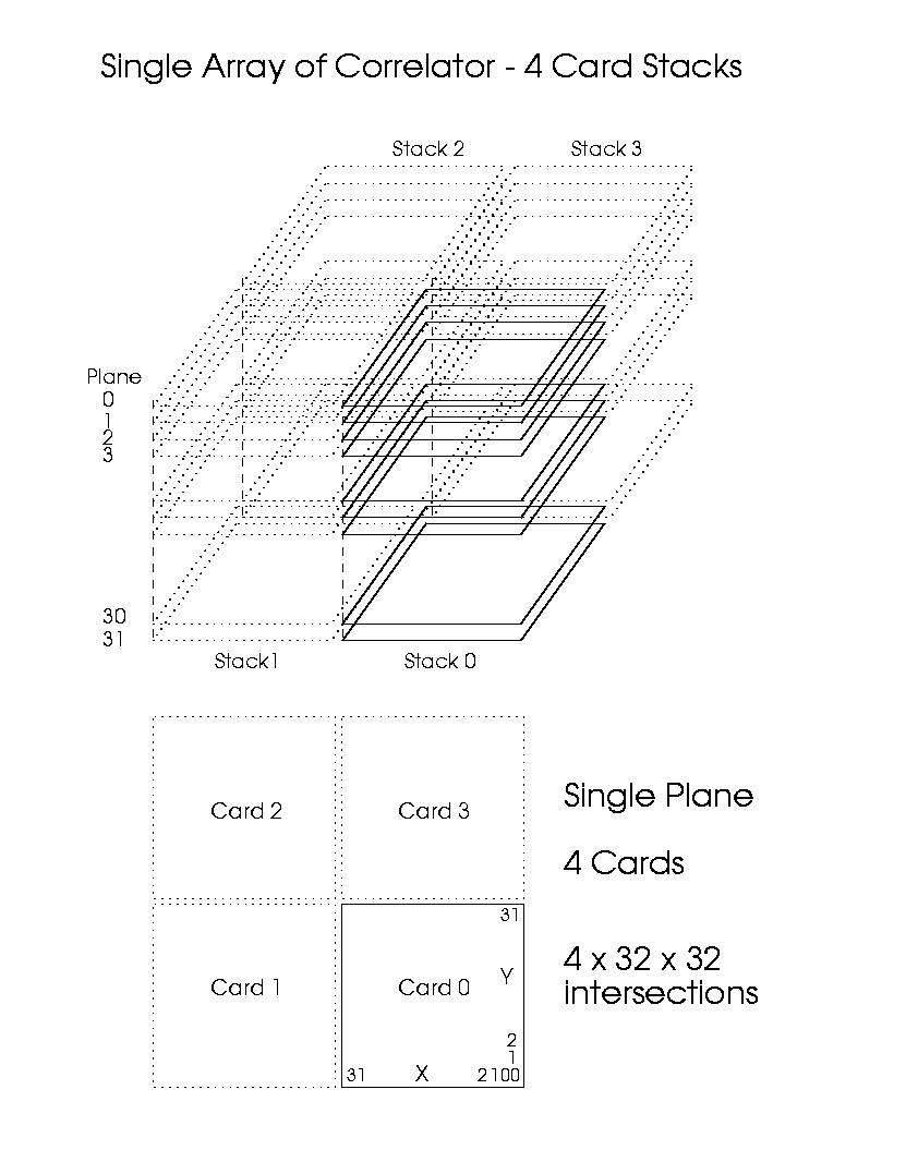
Note: each correlator card has 8 × 8 correlator chips, with each chip correlating 4 × 4 pairs of inputs and outputting 512 lag products at each antenna pair intersection. The spec of 512 products per intersection is for the ``upgraded'' chip design - the current baseline design has only 256 products. We will be considering only the upgraded 512-product design here. Note that the real transform (FFT) takes the lags and leads and outputs the real and imaginary visibilities, and so we will usually talk about the 512 lag products and 512 visibility channels rather than 512 leads and 512 lags or 512 real and 512 imaginary visibilities.
At each intersection XY of the correlator, there is the option to split the
512 lags between the resulting products of the input polarizations (A,B)
depending on mode. For example, all 512 lags could be
devoted to the product AA - we will call this polarization correlation
mode A. Or, we could devote 256 lags to each of the self-correlations
AA and BB, which we will write as AB.
Finally, we could split
the 512 lags into 128 lags in each of AA, BB, AB, BA for full polarization,
assuming (A,B) are different polarizations of the same sideband,
which we will write as AB. Note that 512 lag products
are always output for every intersection XY (actually 512 lags in XY and
512 leads for YX, which will go into a 1024-lag real transform).
Note that when using polarization correlation modes beyond (A), the lags
for the different products will likely come consecutively out of the
chip, eg. lags 0-127 for AA followed by 0-127 for BB in dual mode
(AB). The computer system must deal with
de-MUXing these,
as well as the more complicated case where the arrays are doing extra
lags for the same baseband pair, in which case the lags from intersection
[X,Y] in arrays I-IV must be brought together and ordered correctly
for transformation by the FFT processor. Of course, the lags and leads
for each intersection must always be fetched and brought together
correctly (ie. packed into the FFT array) in all modes.
The other dimension of the correlator is the 32 planes. The vertical ``stack'' of interections XY (or ``baseline stack'') deals with the samples sent down by the MUX. These 32 planes may be needed for summation in the highest bandwidth mode where the 32 planes of the stack contain different 4 GHz samples for the same sets of 512 lags, or halving by factors of two corresponding to the decimation of the digitized stream at the antenna, they may be 32 different sets of 512 lags for the same 125 MHz samples. For example, for the former case, with a single polarization and sideband product AA at the full effective 4 GHz sampling, the 32 planes sum to provide a total bandwidth of 2 GHz and 512 channels of width 3.9 MHz. The same sampling rate but in dual polarization mode we could correlate AA and BB to give a 2 GHz bandwidth but 256 channels (7.8 MHz resolution). Finally, full polarization (AA,BB,AB,BA) would give 2 GHz in 128 channels (15.6 MHz resolution). On the other hand, for the latter case, there are 32 sets of the 128, 256 or 512 lags (depending on polarization mode) which will get transformed into 32 times higher frequency resolution.the 32 planes could contain the same 125 MHz sample stream and they could be ganged up to provide 32 consecutive 512 lag products for a total of 16384 lags, for our combination AA, and thus our bandwidth would be 62.5 MHz with resolution of 3.8 kHz. If the the four arrays of the correlator are ganged up so that they compute further lags for the same signal, a total of 65536 lags for XY! Note that other combinations in between these extremes are available depending upon the baseband-pair, polarization correlation, and plane addition modes chosen.
At the output of the correlator card-stack handling 32 antennas there are thus
which are transferred to the LTA every 16ms. Note that in this 16ms all the cross-products and auto-correlations must be passed, or 16 consecutive 1 ms samples of the auto-correlations only when in AUTO mode. Those modes are set for each antenna. These transfers are done at a rate of one result per 20 ns.
Note that there are always 512 lags × 32 planes or 16384 results per baseline-stack XY regardless of the polarization mode or spectral mode chosen. In the adder tree, however, these can be summed if needed for increased bandwidth depending on the mode, and extra lags from the intersections in different arrays might need to be combined before the FFT stage if increased spectral resolution is desired.
Present plans call for 16 LTA "cards" plus four final adder tree cards plus interface (FPDP) to VME per array. Thus, each array will have four LTA output data streams, to be transferred to the VME system on a minimum of one interface per LTA output stream. Each stream provides the results from one of the 32 × 32 antennas × 32 plane card stacks (one of the 4 correlator cards in all planes) in an array. There are plans to include an extra FPDP interface (initially disabled) for each LTA output stream, so that in principle later on the output rate can be doubled. For the full correlator, there will thus be a minimum of 16 interface streams to the VME, and 32 if the second FPDP is used.
The LTAs accumulate the correlator results in 4-byte (32bit) RAM for integer numbers of the 16ms basic accumulator interval, which are transferred through the adder tree which combines these (as per the mode mask) into the FPDP. The adder tree can add groups of 2M of the 32 planes together for increased bandwidth at the cost of spectral resolution. If all 32 planes are added together (as per mode M=0 for 2 GHz bandwidth) to produce 512 channels per baseline, 524288 4-byte results are available each accumulator cycle (N × 16ms), thus giving a maximum rate of 131 MB/s (N=1). However, if each plane is distinct (mode M=5, bandwidth 2GHz/32 = 62.5 MHz) then there are 16777216 4-byte results!
The FFT computer gets its data from LTAs through the Front Panel Data Port (FPDP), at least in the current design. Eventually, we may have enough bus throughput and CPU power to deal with the correlator output (with its 1ms results) directly, but at first we will need the FPDP buffering. The present design, as described in the previous section, has 4 output streams per array. Thus, one card-stack serving 32 × 32 antennas might (for instance) output 1 stream. There is provision to double the number of streams - this might be desirable as is shown below.
The LTA output RAM buffer results are currently set to be readable in a "window" once every 80ns. Chuck Broadwell thinks it will be relatively straightforward to make these available every 20ns (the correlator to LTA transfer rate). At 80ns per result per stream, the time to clear the cross-products from 32 × 32 antennas using 1 stream is
while if we can read 2 output streams per stack the the data can be cleared in 21 ms and 671 ms respectively. Thus, even with 2 streams per card-stack, we cannot get all of mode 0 in less than the minimum accumulator time of 16 ms. If we could retrieve results from each FPDP in a streaming rate of 20 ns per stream, 1 stream per stack would fetch all of adder tree mode 0 in 10 ms, and 2 streams would get us to mode 1 ( 1024 chan, 1 GHz total bandwidth) in 10 ms.
The desire for faster LTA output must be traded off against the increased data rate. For example, assuming one stream per stack, in going from 80ns to 20ns the sustained data rate that the FPDP to computer bus must deal with goes from 4 bytes/80ns = 50 MB/s, which is still fast for VME, to 4 bytes/20ns = 200 MB/s which is really scary. However, if 2 streams per card-stack (8 per array, 32 total) were used, then the bus would need to run at 40 ns per result (100 MByte/sec) on each of the interfaces in order to clear all of mode 0 in 10 ms.
It is likely that even 80 ns per stream is too fast, and more streams may be necessary. For example, if we read 4 streams per stack (16 per array, 64 total), and read every other 80ns interval (160ns), each bus (stream) would have to deal with only 25 MB/s, which is within the capabilities of VME (Barry's number of 80 MB/s, with some nominal overhead), and each stream would clear its 1/4 of a card-stack in mode 0 at
which is within two 16ms accumulator cycles.
How the LTA and adder tree output is divided up depends on the details of the lag correlation mode chosen. Since as fewer planes are summed together when increasing the spectral resolution (mode M, M=0,1,...,5, 512 × 2M lags per intersection), the numbers from the same vertical ``stack'' of intersections will need to be shuffled into the same output stream for transforming to frequency channels (see below). Four streams per quad nicely breaks down to one stream per quarter card of 16 × 16 antenna pairs through all planes. However, the complexity of using a slow bus and many parallel streams may be excessive, and it may in the long run be better to have one ultra-fast stream into a fast bus.
The scientific case for the correlator specs was presented by Rupen, Shepherd & Wright in their February 1998 White Paper. They assumed that the correlator could dump all the cross-products every 16ms, and all the auto-correlations every 1ms. Furthermore, they assumed that the inputs to the correlator were configurable such that baseband pairs (up to the maximum number available, 4 here) were tradeable for polarizations and frequency channels. In particular, the schedule has the first quarter of the correlator being delivered in 2004, which should be able to service all four baseband pairs from half the number of total antennas (32).
In the current design, one quarter of the correlator is a single array, which is normally one baseband pair for all 64 antennas. Antennas and polarizations are treated differently - any stream for a given antenna must go to at least one row and one column of the 4 cards in a plane and thus some adjustment must be made to allow the baseband pairs to be traded for antennas. It appears that this is possible using some extra hardware. It should be pointed out that this will be critical for operation of the array with the fewer than final number of antennas as they are being delivered. Being able to correlate a single baseband pair for a reduced number of antennas would overly degrade the sensitivity so as to compromise the first science out of ALMA.
There may also be some longer-term benefits for having this flexibility built in, especially if the ALMA operates with a number of simultaneous subarrays (eg. total power on 4 antennas, a VLBI subarray, a compact subarray in wideband continuum mode and the long baselines in high resolution spectroscopy mode, all at the same time).
The desired data rates are on the edge of what is easily accomodated in general purpose computers (with a substantial number of processors working on each array output). Basically, the 512 × 2 lead and lag results for each baseline stack (the 32 planes summed for mode 0) must be transformed to produce 512 × 2 real and imaginary visibilities in that frequency channel. Assuming a bus rate of one result per 160ns, all required numbers could be delivered in
and thus the FFT for that 1024 word array needs to be completed by the the time the next batch of lags is available 164µs later. This assumes the FFT computer works serially on the FPDP stream. These could be further divided between processors if needed.
If dual polarization (or dual sideband), or full polarization are desired, then the number of lag products to transform (for a given bandwidth) will be smaller, 256 for dual, and 128 for full polarization for mode 0. For full polarization, we will be doing 256-long transforms (128 lags and 128 leads). On the other hand, if the arrays are ganged together to increase the number of lags by a factor of 2 or 4, then not only will the transforms be longer but the lag products to go into the transforms will be necessarily coming for different streams, and thus one CPU cannot service only one stream.
Note that the 1-D Cooley-Tukey radix-2 FFT algorithm can transform $N$ (power of 2) numbers in
operations which for N=1024 is 51200 floating operations. To transform this in 164µs requires 312.5 Mflops. In other modes presumably the arrays to be transformed will be correspondingly longer, and the time to accumulate them will thus be linear in N. Since log2 N = 10 for mode 0, the number of operations required will also roughly grow as N, and thus I expect a design that can handle mode 0 can also keep up with the other modes.
As pointed out in the more comprehensive memo by Jim Pisano (15 Sep 1999), the data also need to be Van Vleck corrected and Hanning windowed, which add roughly a factor of two to the numbers above. It appears that using the FFTW package (http://www.fftw.org) operational FLOPS of 3Nlog2 N can be achieved for the FFT, or 6Nlog2 N for the total set of operations.
Here are several example observation modes that I have come up with:
Maximum bandwidth 16 GHz continuum observations at 30 - 46 GHz or 84 - 100 GHz, single polarization, double sideband. This might be expected to be the main mode for spectral analysis of (unpolarized) nonthermal sources. Both sidebands are used and the bands aligned consecutively (I'm not sure what the gaps between bands, especially between sidebands, will be). In this mode, each intersection XY correlates the sidebands U and L in polarization AA with 256 lag channels for each. The channel resolution is 2 GHz/256 = 7.8 MHz. Note that since this channel resolution implies a velocity width of 78 km/s at 30 GHz and 28 km/s at 84 GHz, this mode would also be useful for searching for redshifted galaxies in CO!
Assuming the receivers have wideband horns whose illumination is set to accomdate the low end of the band, then the primary beam will have a width
for 12 meter antennas, giving 3.13' FWHM at f = 30 GHz and 1.12' FWHM at f = 84 GHz. If the source is large and we want to OTF scan at a rate of 0.5 degree/sec, then we are moving 10 beams/sec at 30 GHz and 27 beams/sec at 84 GHz, and thus need to sample at roughly 3 per beam or 30 Hz or 80 Hz respectively. This implies maximum accumulation times of 33 ms and 13 ms respectively. Note that at 30 GHz this scan speed allows us to use 32 ms as an accumulator time with no problem - 4 streams per quad (32 × 32 ant) at 160 ns would clear all 524288 results in 21 ns as shown above. On the other hand we see that for 0.5 deg/sec scanning at 84 GHz, even the minimum correlator dump time of 16 ms would be marginal, and the time to clear the data in 4 streams at 160 ns is even further off, though 8 streams per quad would get us clear in 10.5 ms. For a dump time of 16 ms (rate of 62.5 Hz), a scan rate of as much as 20.8 beams/sec at 3 samples/beam could be supported. Note that the ALMA spec for OTF in cross-correlation mode is only 0.05 deg/sec (3'/sec) anyway, which at 30 GHz translates to just under 1 beam/sec, and 2.7 beam/sec at 84 GHz, which are well under the dump limit.
Note that our expected rms noise level at 95 GHz for 32 antennas is expected to be only 7.5 mJy at 30 GHz and 13 mJy at 84 GHz in a 7.8 MHz channel in 1 s (using the sensitivities given in the Butler & Wootten Proto-Memo). If, for example, at 84 GHz you are looking at CO(2-1) at redshift z=1.74, then the expected flux in 7.8 MHz (25 km/s) is about 0.76 mJy (using numbers from Memo 243) and it would take 295 sec to reach S/N of 1 and 78 minutes to reach S/N of 4). Assuming the normal cal cycle of 10 sec on-source, 1 sec slew, 1 sec on calibrator, it is unclear whether anything would be gained by OTF scanning over just integrating on-source for 10 seconds (with probably 1 second integrations). OTF scanning at 0.05 deg/sec is unlikely to be fast enough to help with gain variations, but should help with the atmosphere.
[More to come]
These are some of the comments and questions I have concerning the system design:
Is it worthwhile to build in the capability to read the LTA every 20 ns now, and either increasing the bus speed to deal with this now, or planning on eventual upgrade? Or is it preferable (and in the long run cheaper) to plan on increasing the throughput by further parallelizing the output buses and FPDPs beyond the 8 or 16 per array currently envisioned? Or both?
Since the maximum channel bandwidth (mode 0: 2 GHz, 128 channels) is 15.6 MHz, bandwidth smearing is not a problem for even the longest baselines (20 km) and lowest frequency (30 GHz) envisioned for ALMA.
It appears that VME bus can deal with an FPDP output rate of 1 per 160 ns. One output stream per 32 × 32 card-stack, or 4 per array (16 total), can clear the mode 0 cross-correlations (524288 results) in 84 ms at this rate, or 5.25 accumulation times. Is this sufficient for the initial operation, given that it is more than 5 times the spec given in Rupen et al.? The science drivers for this rate in cross-correlation mode seem to be pulsars and OTF scanning. If the provision is there for eventual increase in the rate (either number of streams or bus rate), is this good enough for the start? Or should we invest now in a faster bus or more streams, or both?
Note that in auto-correlation mode, we get 32 antennas × 16 = 512 products × 512 lags = 262144 results per quad per accumulation time, which is half the cross-correlation rate. Thus, 2 streams at 80ns (4 streams at 160 ns) per result can clear the auto-products in 10.5 ms. Thus, the OTF specs presented in Rupen, Shepherd & Wright are satisfied. But the initial one stream at 80ns is a factor of two too slow.
I assume the 8 digitized streams from each antenna can be selected between polarizations (E,H) and sidebands (U,L) for each baseband pair. Are they fully configurable, so you can send everything (E,H) × (U,L) for only two of the four baseband pairs? This would seem to give maximum flexibility. Are there science drivers for this?
In Memo 190, it was stated that the 256 lag chip would be able to provide a maximum of 1024 lags ( + 1024 leads ) per baseline, which translates to 2048 lags ( + 2048 leads ) with the 512 lag chip. This is done by ganging the four arrays to compute extra lags for one baseband pair instead of correlating a different baseband pair. To get the lag delays right, the signals from the first array, after passing along the rows and columns, would be sent into the next array. Because this also means that lags from more than a single array must be fetched to do a given baseline's FFT makes the computing system more complicated than needed if all of a given baselines correlations occur in only one array. Is the spectral resolution attained without crossing arrays (16384 channels over 62.5 MHz, 3.8 kHz per channel, or 38 m/s at 30 GHz and 10 m/s at 115 GHz) sufficient for the science drivers, or is the extra factor of 4 resolution worth the added complexity?
Note that if full configurability of board inputs was available, then the correlations could be adjusted so that all results for a given baseline were done in a given array (or a given card-stack if the extra channels are not needed for the baseband pair).
Is there any way to transmit down both R and L for both sidebands of all 4 baseband pairs? This will take 16 streams per antenna, and at the correlator station would then be divided down to polarizations (A,B). A later expansion could then double the correlator (add an additional 4 quadrants). This would enable full polarization for a single sideband, or dual polarization for both sidebands. Are there science drivers to require that we be able do to full (or dual) polarization for both sidebands of all pairs?
Should the capability to trade antennas for baseband pairs be part of the overall correlator design, and not just a fix for the first quadrant? It is not unlikely that budgetary constraints will lead to having less than 64 antennas in the final US/European array. It might be good to be able to use some of the spare antenna inputs for extra things.
What are the implications of being able to subarray? In particular, are there restrictions built in to how the subarray must be allocated? For example, it would seem to me that the minimum block that can be allocated to a subarray is that which feeds a given adder tree / FPDP stream. Also, if the arrays for a certain subarry are planned to be ganged together for extra resolution, then the correlator has to know to take the signals from array 1 to feed consecutively to the other arrays. Is this a problem? Is the ability to subarray totally under control of the software interface to the correlator and real time system?
It appears that this correlator design meets all the desired specs, and our current limitation is the handing of the LTA output for FFT and post-processing. The only things the correlator and related real-time system seem to restrict are the fundamental sampling rate (125 MHz), minimum dump time (1 ms auto-products, 16 ms cross-products), and the number of lag products per intersection (512).
Is it possible to increase the bandwidth further by doubling the number of planes to 64, and changing the sampling rate at the antenna to 8 GHz = 64 × 125 MHz? This might be a desirable eventual upgrade.
Is the limitation of the dump time fundamental enough to warrant desiring to access the correlation products at their maximum rate of 1 ms (bypassing the LTAs)? Are further speed increases necessary above that? For example, faster scanning would be allowed for cross-correlation if this were the case.
Is the spectral resolution of this correlator design too limiting? More planes at the current sampling rate would increase the resolution. Going to an FX design might also build in more flexibility, but at maximal cost.
Given the above, should ALMA be planning on an advanced correlator at all, or should the project focus on improving other things such as receivers?
Figure 1: Diagram depicting the relation between the cards in a plane, and card-stacks in an array. (Postscript available)
Figure 2: Diagram depicting a single intersection XY, and the baseline stack of XY through the 32 planes. Note that depending on polarization correlation mode, the products AA, BB, AA and BB, or AA,BB,AB,BA can be carried out to form the total of 512 lags per intersection from a given baseline stack. (Postscript available)
Note: A Postscript version and LaTeX source for this document are available.