![[NRAO]](nraologo1.gif)
|
|
7th NRAO Synthesis Imaging Summer School - June 2000 | Prev |
| Error Recognition - S.T. Myers | Page 23 | |
| Next |
| 18 | Polarization: | ||
| |||
Polarization imaging has its own set of problems. The instrument
measures the signal in two (nominally orthogonal) polarizations, and
the total intensity is constructed by summing these. One of the
Stokes parameters is given by the difference between the two channels,
while the remaining two stokes are synthesized through the
cross-polarization products. For example, on the VLA, R and L are
measured, and thus the correlation products are RR,LL,RL,LR. Stokes
I is constructed from RR+LL, Stokes V from RR-LL, and Stokes Q and U
from RL+LR and RL-LR.
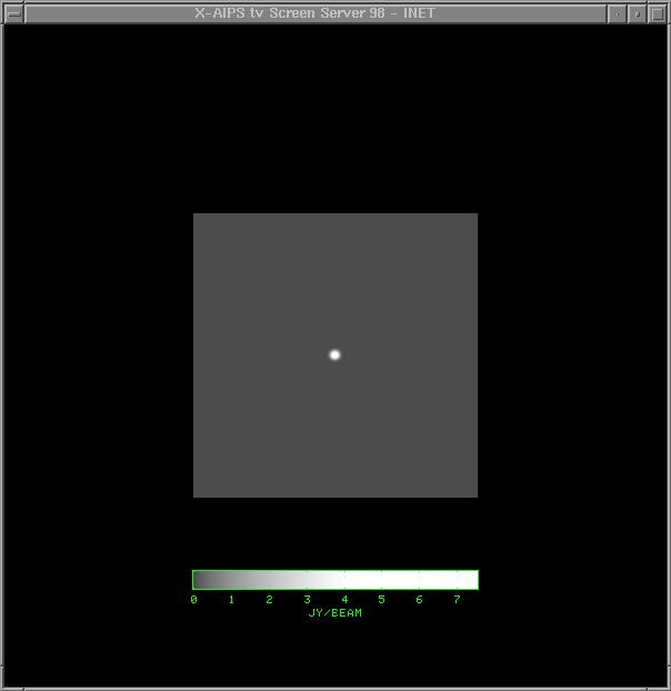
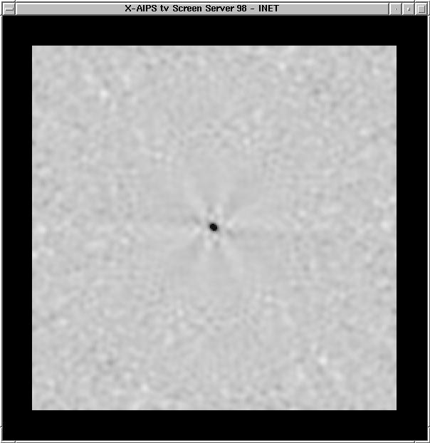
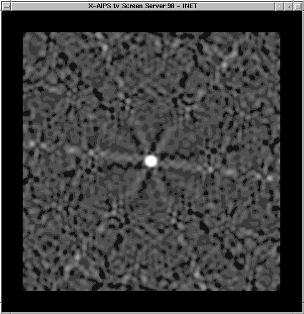
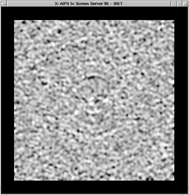
Note that there is no noise visible in the ICLN image (the noise level is a few mJy with the peak at 7.5 Jy), but the polarized emission is much weaker. Sidelobe patterns can easily be seen. Note that there is no discernable circular polarization in the VCLN image at the right, as is expected. The Q, U, and V images can be positive or negative - MEM beware! This data was processed in AIPS. | |||
| Next Page: More Polarization | |||