ALMA-US Strawman Configuration Designs
(Toronto URSI Workshop, Sept. 1999)
What Drives the Array Design?
Science:
- Resolution:
One of the prime scientific goals is the
detection and resolution of extra-solar planets and protostellar
systems, either by direct imaging or by accurate astrometry.
Subarcsecond imaging capability is a key scientific driver for
ALMA, and a configuration with baselines of 10 km or longer is
essential.
- Sensitivity:
ALMA should deliver an order of magnitude
improvement in sensitivity over all existing millimeter arrays.
Excellent brightness sensitivity is highly desirable capability,
and a close packed configuration is also required. A robust
response of the configurations to tapering is another desirable
quality since tapering of data may be unavoidable for
multi-transition or multi-frequency analysis.
- Mosaic and Short Spacing:
The homogeneous array concept
requires that the antennas be fairly closely packed (1.3D) in order
to be able to measure spatial frequencies in the range of the
antenna diameter (see Cornwell 1988, A&A, 202, 316).
Since mosaic imaging is expected to be used a common and a popular
observing mode for ALMA, the configuration design should include a
provision for excellent short spacing data. An added concern over
shadowing needs to be addressed, either incorporating an elevation
restriction or by an N-S elongation.
- Image Fidelity & Dynamic Range:
High image fidelity is
essential for multi-transition studies and continuum spectral index
studies. High dynamic range is needed for most imaging studies,
particularly for imaging bright objects such as planets. An array
design that produces a well behaved synthesized beam and thus
allows successful deconvolution is highly desirable for achieving
this goal. The synethesized beam need not necessarily be
a Gaussian, however.
- Fourier Plane Coverage:
The large number of array
elements for ALMA (e.g. 64) ensure an excellent instantaneous
Fourier Plane (FP) coverage in general. Unlike the existing arrays,
the image quality is then limited by the extrapolation in the
gaps of the FP coverage rather than by the crude sampling of
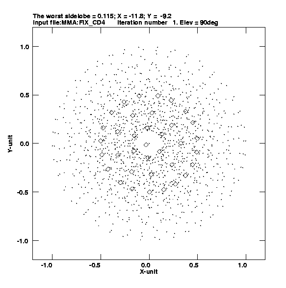
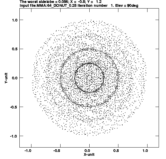
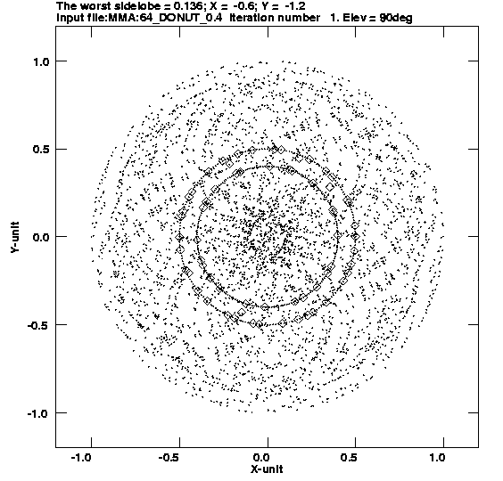
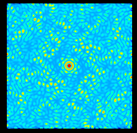
the visibilities. A ring-like configuration yields a nearly
uniform Fourier plane distribution and thus offers a highly
desirable characteristic (see
Woody 1999, MMA Memo 270). It also offers the best
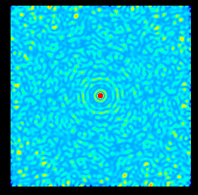
resolution of sources near the resolution limit. The synthesized
beam has large close-in sidelobes, but
the sidelobe suppression algorithm developed by L. Kogan is shown to be
highly effective (see below).
Operation:
- Minimizing Pads, Cabling, & Road:
Requring maximum re-use of pads and cabling for the purpose of
minimizing the construction cost can have a strong influence in
the array design.
Should the imaging capability and sensitivity of the array be
compromised to reduce the cost of construction and maintenance?
If so, what is the acceptable level? For the purpose of this
strawman array design exercise, some efforts are made to minimize
these costs but only after determining which types of array
designs offer the desired imaging and sensitivity characteristics.
This can become a potentially important issue and may need to
be reconsidered if the cost of each pad runs as high as $100K.
- Ease and Speed of Reconfiguration:
Should the imaging capability and sensitivity of the array be
compromised in favor of the ease and speed of reconfiguration?
If so, what is the acceptable level? Related issues are:
(1) can we afford to station a full time, permanent reconfiguration
crew at 16000 ft; (2) how can we minimize the number of hours lost
during reconfiguration and subsequent calibration; and (3) how
can we maximize the utility of the limited manpower?
- Dynamic Scheduling:
ALMA be able to reconfigure quickly
to take advantage of climatic changes. The VLA-like set
configurations do not allow such flexibility. A telescoping array
also requires N(antenna)/N(mover per day) days to reconfigure --
over two months if there are 64 antennas and only one antenna can
move each day! Further, a telescoping array introduces an additional
layer of complication to the scheduling of observations as
well as reconfiguration.
- Array Efficiency:
Can we afford to trade the scientific
output of the array with the ease of the array operation? Set
configurations are easier to plan and execute, but a greater
loss of overall efficiency may occur by requiring more data to
be tapered (see below).
- Redundancy:
Some redundancy can be useful for
cross-calibration. On the other hand, this causes sidelobes to pile
up at particular locations. It might be better to distribute the
error instead. Are the trade-offs sufficient to warrant building
in some redundancy in the design?
Cost-Benefit Analysis (MMA Memo 199 & 265)
The cost and benefits of adding an additional configuration are
formulated and computed by Holdaway (1998, MMA Memo 199) and
by Yun & Kogan (1999, MMA Memo 265). See these memos for details.
One of the main conclusions of these memos is that some 4 to 6
separation configurations can achieve the optimum
array efficiency at the minimum cost. Modest changes to the
assumptions made in these analyses should not change this conclusion.
The strawman array design discussed here utilizes this finding.
Kogan Optimization (MMA Memo 171)
Keto (1997, ApJ, 475, 843) and others have previously argued for
array designs that optimizes the FP coverage. Such a design
makes a good sense for the arrays with small numbers of
elements (e.g. <10) since the image quality is limited by
how well the visibility can be measured with the limited
sampling of the Fourier plane. When the numbers of the
array elements are as large as 64, then even the instantaneous
FP coverage should be very good, and a different optimization
critiria may be more important.
Kogan (1997, MMA Memo 171) suggests an alternative array optimization
scheme which minimize the sidelobe response within the certain
numbers of synthesized beam radii. By minimizing the sidelobe
responses, this optimization aims to allow the best possible
performance for any deconvolution methods, such as CLEAN or MEM.
See the memo for the full mathematical desciption and how this
algorithm is implemented in practice.
Using a mathematical proof, Kogan (1999, PASP, 111, 510) also
demonstrates
that the negative sidelobes of an array's synthesized beam in a
snapshot observation depends only on the number of the elements.
For a 64 element array, the maximum negative sidelobe level should
be about 1.6% for a snapshot.
Competing Reconfiguration Concepts
Set Configurations:
|
Pros |
Cons |
|
|
|
simple reconfiguration and scheduling planning |
a larger moving crew is needed |
|
tapering of data can be designed in |
tapering may be needed more often |
|
3-6 days are required for each reconfiguration,
but this time can be utilized fully for detection experiments |
Continuous Reconfiguration:
|
Pros |
Cons |
|
|
|
minimum moving crew is needed |
permanent moving crew is needed |
|
continuously changing resolution |
not necessarily more robust against tapering in practice |
|
maximum pad re-use can be designed in |
N+1 antennas always lost for calibration |
|
|
additional layer of complication in scheduling observations and reconfiguration |
==> consider a hybrid scheme?
Practical Concerns
Site:
- Topography:
Cerro Chajnantor, Cerro Chascon, as well as
the quebradas and local gradient limit where the pads can be placed.
In general, all concentric configuration with larger than 3 km diameter
will have difficulty getting around these topographical obstacles (see
below).
- Gas Pipeline:
Similar to above but man-made. The three
crossing points are already negotiated.
- Science Reserve Boundary:
Not a hard limit as it could
potentially be changed with some effort.
Logistics:
- Post-move Calibration:
measuring delays, pointing, baselines,
etc. This could have an important impact on overall array efficiency as
some of these measurements require 3-6 antennas at once and take more
than 2-3 hrs (see
Yun & Kogan 1999, MMA Memo 265). While a post-correction is possible
for any baseline errors, an antenna is useless until its delays and
pointing model are determined. This also has a serious impact on the
real time data pipeline processing.
- Cost of Additional Configuration:
The cost of one additional configuration is approximately $5-10M, comparable to the cost of 1 or 2 antennas. Trading the cost of one or two antennas for an additional configuration may be easily justifiable if the array capability can be significantly improved.
- Cost of a Transporter:
Estimated to be about $1M each.
Should this impact the array design? Regardless the type of
intermediate configuration design we adopt, the reconfiguration to and back
from the "10 km" array will require enough transporters to carry this
out in a reasonably short time. Reconfiguring from the 3 km configuration
to the 10 km configuration will take approximately 3.5 hr per antenna
assuming an average one way travel distance of 15 km. To complete
this reconfiguration in 6 days, we will need at least 5 transporters
if each transporter can move 2 antennas per day (8 days with 4
transporters). If we had only 2 transporters,
this reconfiguration will take 16 days!
- Weather:
Wind (and snow/rain) may offer a major challenge to any reconfiguration plan (see
Holdaway & Owen 1995, MMA Memo 147). The site characterization
data suggests a strong diurnal variation in wind speed (see
Holdaway et al. 1995, MMA Memo 159), and a windy condition is
common in the afternoons.
- Cycling Time:
How often should we return to a particular
configuration? At least once around the full configuration cycle
each year, but a phase shift needs to be incorporated to allow for
the celestial seasons. The largest configuration may only need to
be visited every other time.
Strawman Arrays
- Surface Brightness Sensitivity
- Mosaic Imaging and Short Spacing Information
- Double Rings with a scale factor between 2 and 4
- Short spacing data in each configuration
- Less concentrated for good FP coverage and angular resolution
- Highest angular resolution
- Uniform FP coverage
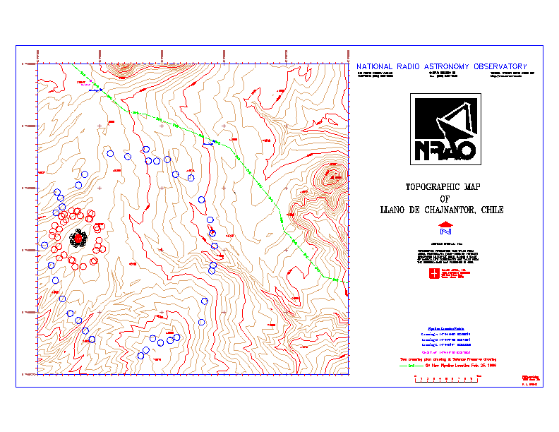
A Strawman Layout at the Site
A layout for a possble set of ALMA configurations are
shown below. This drawing is the output of an exercise only meant to
demonstrate how a potential ALMA configurations may be
matched to the site topography and other restrictions. At the moment, only
limited
topographical information sufficient for 3 km array is
available, but additional information should become available shortly.
An important outcome of this exercise is that there are limited
options for a 500 meter diameter flat area at the
site, which makes fitting any concentric or spiral type configuration
difficult. The 10 km configuration will most certainly have to be
independent of the more compact configurations.
Remaining Tasks
Imaging Study (Simulations & Evaluations)
- Mosaic imaging
- FP coverage: sidelobes and deconvolution
- Snapshot versus earth rotation synthesis
Site Study
- Location of the compact array (which determines how the
remaining arrays may or may not fit into the site constraints)
- Largest configuration allowable and its geometry with respect to the topography
- Soil study (e.g. much cheaper to put pads on bedrocks)
Detailed Optimizations
- N-S extension & Hybrid Arrays
- Operational details. For example, some 3-6 antennas (5-10%)
may be unavailable at all times either due to failures or for
reconfiguration.
Last modified September 15, 1999
myun@nrao.edu