ALMA Strawperson Donut/Double-Ring A Array
Physical Descriptions:
- Maximum baseline 3000 m
- Minimum baseline 85 m
- Maximum near-in sidelobe 4%
- The outer sidelobes are strongly suppressed by earth rotation synthesis
(less than 1.6%).
Pad Positions:
Pad positions are given here in meters. The X and Y positions
are with respect to a reference position on the 5 degree mask.
To convert to SAM56 coordintes:
SAM56 E = 624820 + X
SAM56 N = 7449700 + Y
Array Layout, UV Distribution, Synthesized Beam (snapshot):
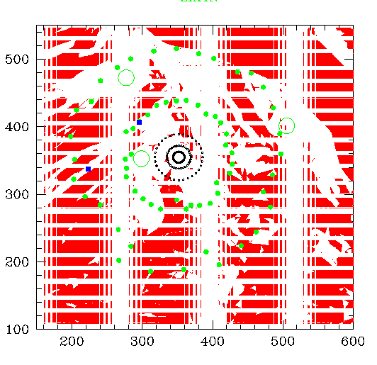
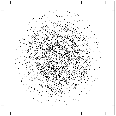
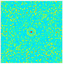
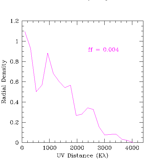
(Upper left panel) Pad distribution shown with the "5 degree slope" mask
in red. Two blue squares mark the current position of the NRAO
test equipment container and the CBI. Horizontal gaps in the mask are the
artifacts of the plotting routine.
(Upper right panel) Snapshot UV distribution and pad postions from CONFI.
(Lower left panel) Snapshot dirty beam. The plotted color ranges between
-5% (blue) and +10% (red).
(Lower right panel) Radial density distribution of the visibility points
for a snapshot observation. Only 0.4% of the UV cells are sampled.
UV Distribution, Synthesized Beam (6 hr synthesis):
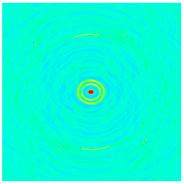
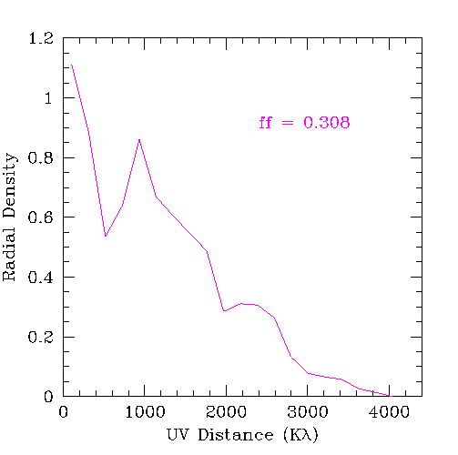
(Left panel) A dirty beam after a 6 hour long earth rotation synthesis.
The plotted color ranges between -5% (blue) and +10% (red). While the near-in sidelobes remain more or less the same as the snapshot case (above), the
outer sidelobes are strongly suppressed by earth rotation synthesis
(less than 1.6%).
(Right panel) Radial density distribution of the visibility points.
About 31% of the UV cells are sampled after 6 hours of observations.


