PIE
TOWN VLBA HOLOGRAPHY SYSTEM
The
holography system measures the complex voltage pattern over the focal plane
of the antenna. The phase portion is obtained by cross correlating
the signals received through the main reflector optical path with signals
received directly in a reference antenna. In this system, the reference
antenna is a horn mounted on one of the feed legs. The voltage pattern
can be transformed to image the aperture plane of the antenna. The
amplitude gives the illumination pattern while the phase pattern measures
fluctuations in the signal path length. Imperfections in the position
of the surface can be deduced from the phases. The ultimate goal
is to adjust the antenna panels based on these measurements to improve
the surface and, hence, the performance at high frequencies.
The
signals observed with the holography sytem are at 12 GHz and are from TV
satellites. Very inexpensive home satellite receivers were used.
The data path uses the normal VLBA 12 GHz LO/IF system and then ultimately
is sampled on a data aquisition card in a PC. The correlation is
done in the PC. Vivek Dhawan has been overseeing the project and
dealing with data analysis. Mike Revnell built the digital equipment.
The mechanical work was done by Jon Thunborg, Steve Aragon, and Ramon Gutierrez
while the electronics were assembled by Vivek, Tom Baldwin and Jim Oty.
Click
on the thumbnail to see a larger version of the image.
|
Thumbnail.
|
Description
|
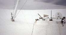 |
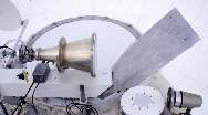
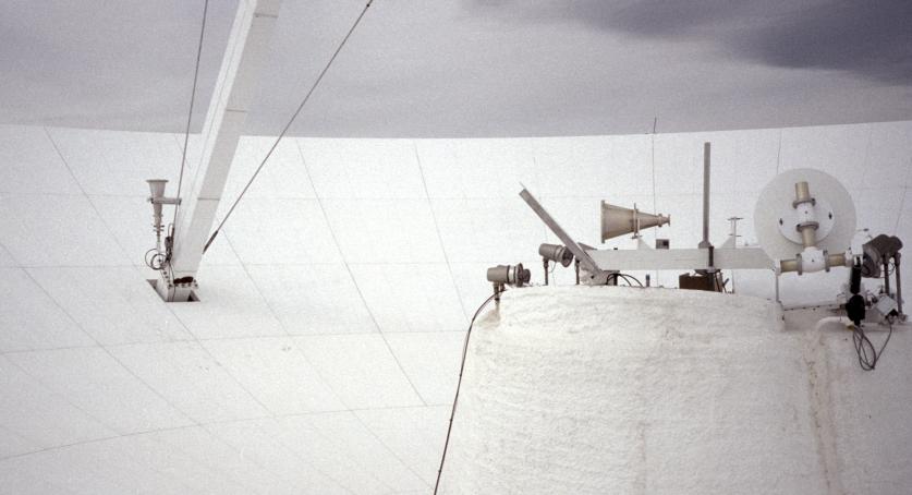
This view shows both the reference horn attached to the
feed leg and the offset horn and reflector that receives signal along the
normal optical path. Click here
for an
even
larger version of the picture. |
 |
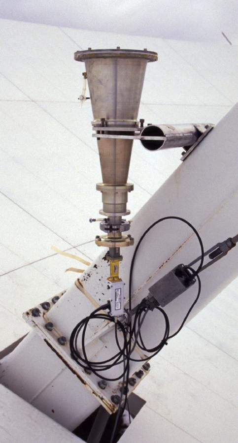
This is a closeup of the reference horn and receiver. |
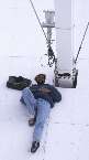 |
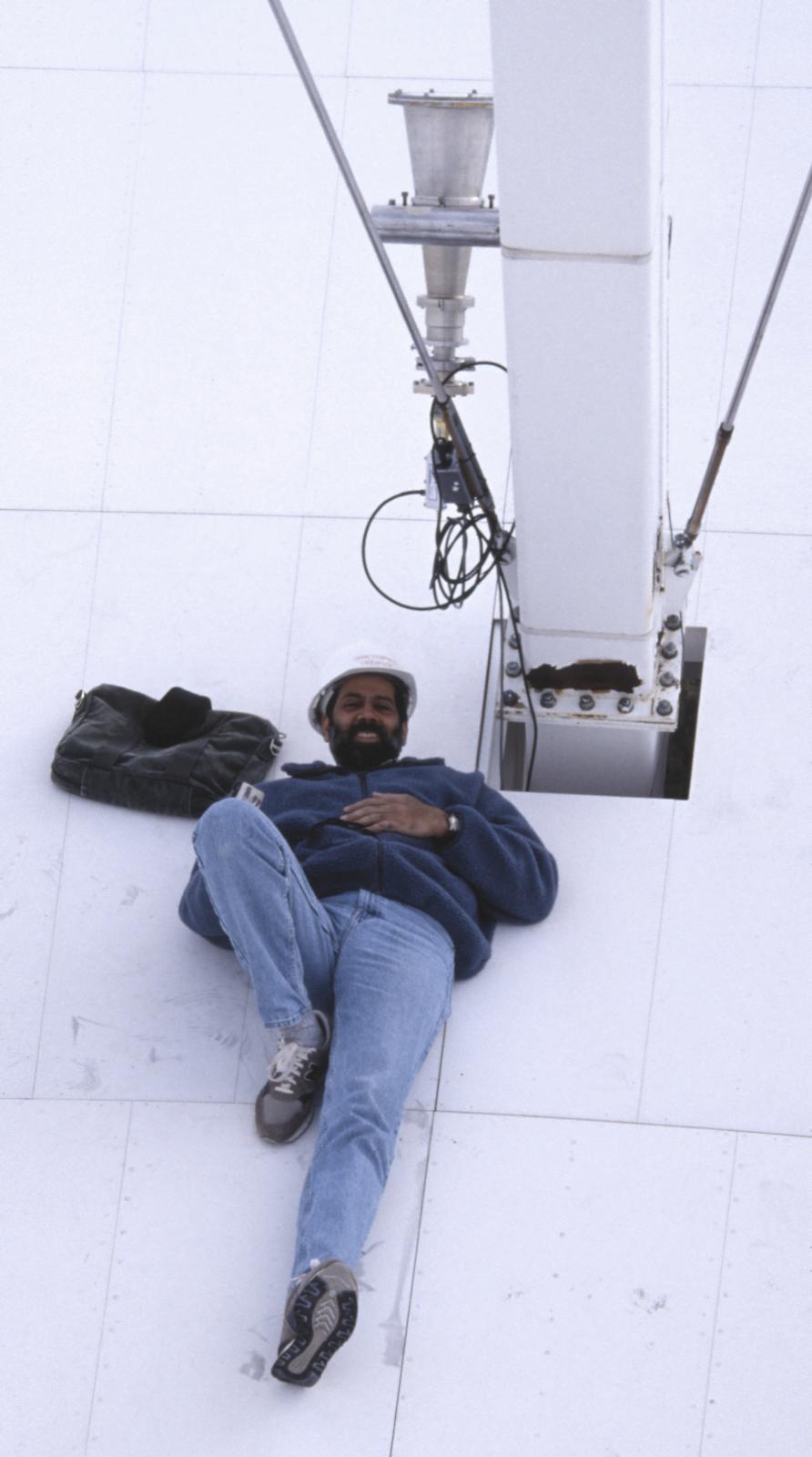
Another view of the reference horn with Vivek lying down
on the job. Actually he is checking the polarization. |
 |
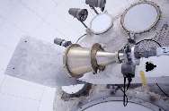
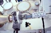
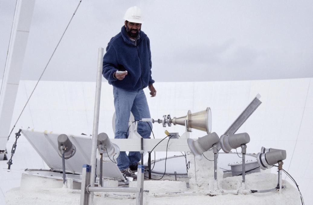
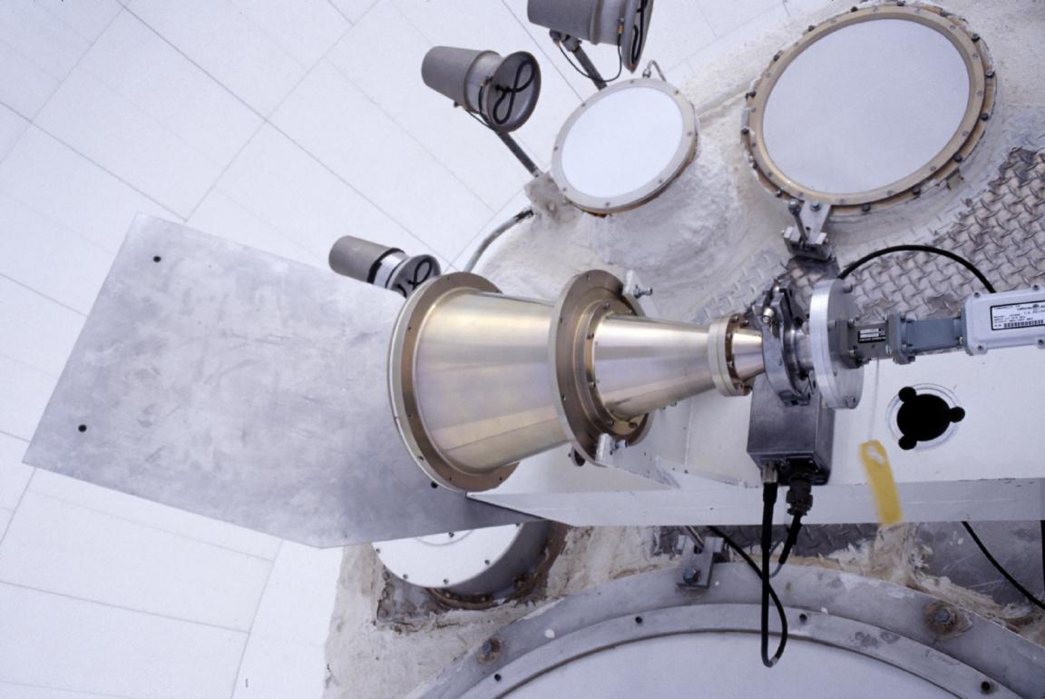
The signal from the main antenna would normally enter a
feed on the feed ring on which Vivek is standing. With the holography
system, the signal is deflected sideways to a horn mounted near the center
of the feed circle. With this scheme, there is no need to move any
of the regular receivers and the system can be mounted quickly for test
observations. |
 |
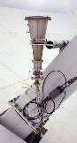
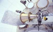
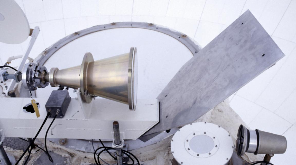
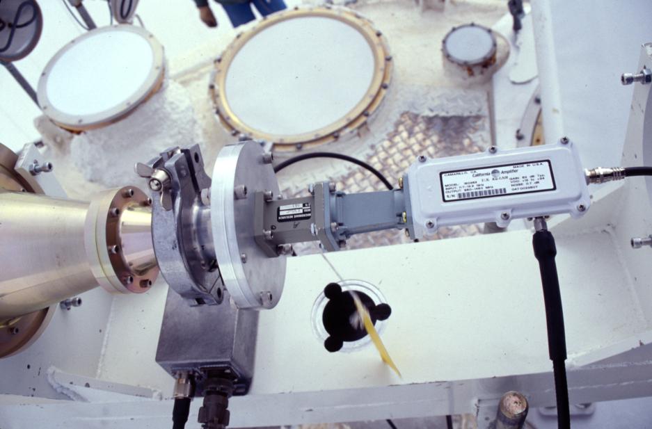
A closer view of the offset reflector, horn and receiver
for the main beam signal. |
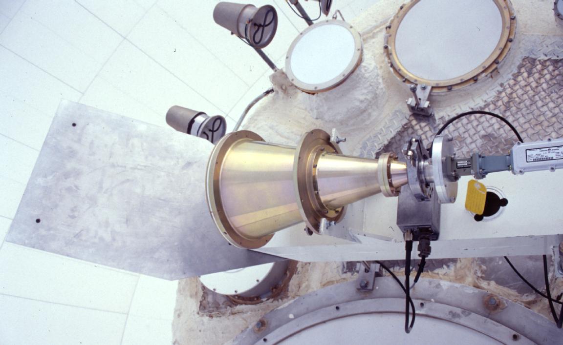
 |
Another view. |
 |
Yet another view. |
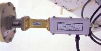 |
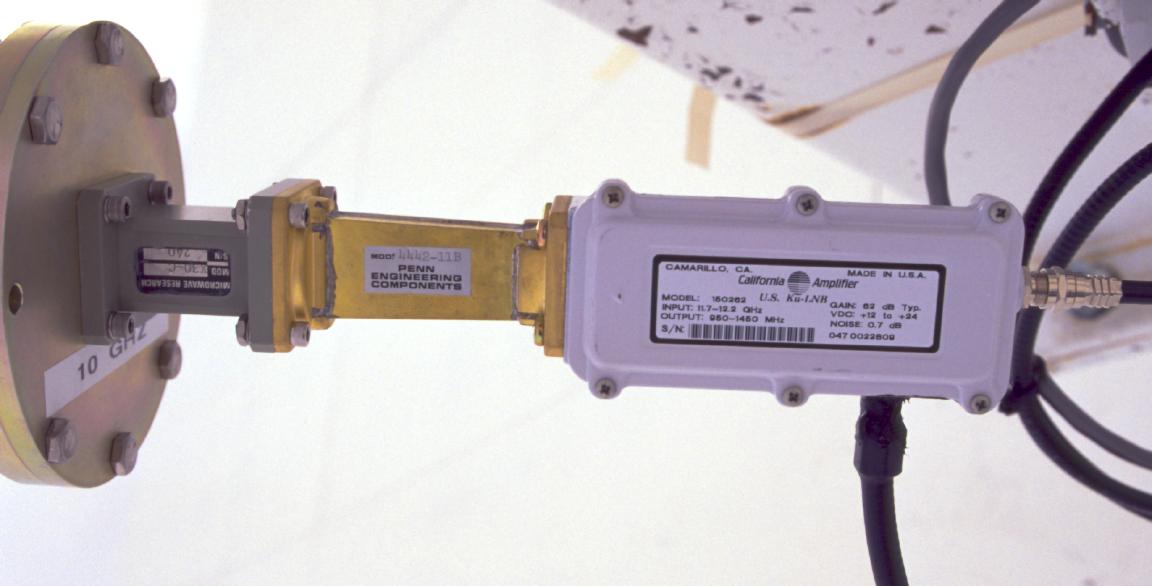
The consumer grade 12 GHz receiver. |
 |
Another view of the receiver and base of the horn. |
|
|